Water-base hydraulic electrostriction high speed switch valve
A high-speed on-off valve and telescopic technology, applied in the field of high-speed on-off valve and high-pressure hydraulic electrostrictive high-speed on-off valve, it can solve the problems of large influence of temperature change and amplification of output displacement of the driver, and achieve small influence of temperature change and output flow rate. Large, high-response frequency effect
- Summary
- Abstract
- Description
- Claims
- Application Information
AI Technical Summary
Problems solved by technology
Method used
Image
Examples
Embodiment 1
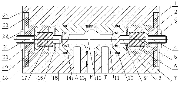
[0026] Embodiment 1: as figure 1As shown, a water-based hydraulic electrostrictive high-speed switching valve includes a water-hydraulic high-speed switching valve, a left electrostrictive driver and a right electrostrictive driver, and the left electrostrictive driver and the right electrostrictive driver are symmetrically arranged on the water The left and right ends of the hydraulic high-speed switching valve; the left electrostrictive driver is composed of an output rod 15, a gland 16, an electrostrictive rod 17, a sleeve 18, a shell 19, a temperature compensation sheet 20, and a base 23, and the base 23 passes through the transition fit into the casing 19, one end of the temperature compensation plate 20 is in contact with the base 23, the other end is in contact with the electrostrictive rod 17 and the sleeve 18, the electrostrictive rod 17 and the sleeve 18 are in clearance fit, and the electrostrictive rod The top of 17 is in contact with one end of the output rod 15, ...
Embodiment 2
[0027] Embodiment 2: as figure 1 As shown, a water-based hydraulic electrostrictive high-speed switching valve includes a water-hydraulic high-speed switching valve, a left electrostrictive driver and a right electrostrictive driver, and the left electrostrictive driver and the right electrostrictive driver are symmetrically arranged on the water The left and right ends of the hydraulic high-speed switching valve; the left electrostrictive driver is composed of an output rod 15, a gland 16, an electrostrictive rod 17, a sleeve 18, a shell 19, a temperature compensation sheet 20, and a base 23, and the base 23 passes through the transition fit into the casing 19, one end of the temperature compensation plate 20 is in contact with the base 23, the other end is in contact with the electrostrictive rod 17 and the sleeve 18, the electrostrictive rod 17 and the sleeve 18 are in clearance fit, and the electrostrictive rod The top of 17 is in contact with one end of the output rod 15,...
Embodiment 3
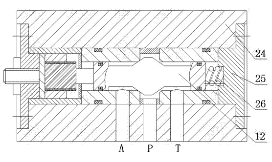
[0028] Embodiment 3: as figure 2 As shown, a water-based hydraulic asymmetric electrostrictive high-speed switch valve includes a water-hydraulic high-speed switch valve, a left electrostrictive driver, a valve cover 25 and an adjustment spring 26, and the left electrostrictive driver is arranged on the water-hydraulic high-speed switch. At the left end of the valve, the bonnet 25 is mounted on the right end of the valve body 24, one end of the adjustment spring 26 is in contact with the spool 12, and the other end is in contact with the bonnet 25; the left electrostrictive driver is composed of an output rod 15, a gland 16, an electrostrictive 17. The sleeve 18, the housing 19, the temperature compensating sheet 20, and the base 23 are composed. The base 23 is loaded into the housing 19 through transition fit. One end of the temperature compensating sheet 20 is in contact with the base 23, and the other end is in contact with the electrostrictive rod 17. contact with the sle...
PUM
 Abstract
Description
Claims
Application Information
 - R&D
- Intellectual Property
- Life Sciences
- Materials
- Tech Scout
- Unparalleled Data Quality
- Higher Quality Content
- 60% Fewer Hallucinations
Browse by: Latest US Patents, China's latest patents, Technical Efficacy Thesaurus, Application Domain, Technology Topic, Popular Technical Reports.
© 2025 PatSnap. All rights reserved.Legal|Privacy policy|Modern Slavery Act Transparency Statement|Sitemap|About US| Contact US: help@patsnap.com


