Vehicular disc brake rotor and manufacturing method of vehicular disc brake rotor

a technology of cast iron and brake rotor, which is applied in the direction of brake discs, solid-state diffusion coatings, mechanical devices, etc., can solve the problems of difficult to secure sufficient salt-bath nitrocarburizing treatment has a problem in terms of safety and environmental load, and the outermost surface of the compound layer is prone to porous layer, etc., to achieve excellent corrosion resistance and wear resistance and friction characteristics, and prevent rust. , the effect o

Active Publication Date: 2014-03-06
AKEBONO BRAKE IND CO LTD
View PDF9 Cites 9 Cited by
  • Summary
  • Abstract
  • Description
  • Claims
  • Application Information

AI Technical Summary

Benefits of technology

[0026]According to embodiments, it is possible to provide the vehicular disc brake rotor having excellent corrosion resistance and wear resistance and friction characteristics that are little changed by influences of humidity and temperature and capable of keeping stable brake performance for a long time and preventing rust from being formed, which deteriorates an outward appearance of the rotor. Thus, the industrial meaning thereof is very great.

Problems solved by technology

However, the coating film or the coating is worn or delaminated over long time, so that it is difficult to secure the sufficient corrosion resistance and wear resistance.
However, the salt-bath nitrocarburizing treatment has a problem in terms of safety and environmental load because harmful cyanide is used.
Also, the salt-bath nitrocarburizing treatment has a problem that a porous layer is apt to be formed on the outermost surface of the compound layer.
However, when the cast-iron friction member having the nitrogen compound layer formed on the surface thereof by the above method is exposed to outside environments over a long period, red rust (Fe2O3) may be formed on the surface due to influences of temperature and humidity.
Regarding this, when the red rust (Fe2O3) is present on a surface of the rotor, it can be securely seen even from the outside with naked eyes, so that an outward appearance of a vehicle is deteriorated.
However, it is difficult to set conditions of the homo treatment.
Thus, when the temperature is too high or the treatment time is too long, the red rust (Fe2O3) is formed.
Therefore, it is very difficult to form a uniform and compact black iron oxide layer over the entire frictional surface of the iron-cast friction member.

Method used


Image

  • Vehicular disc brake rotor and manufacturing method of vehicular disc brake rotor
  • Vehicular disc brake rotor and manufacturing method of vehicular disc brake rotor
  • Vehicular disc brake rotor and manufacturing method of vehicular disc brake rotor

Examples


example 1

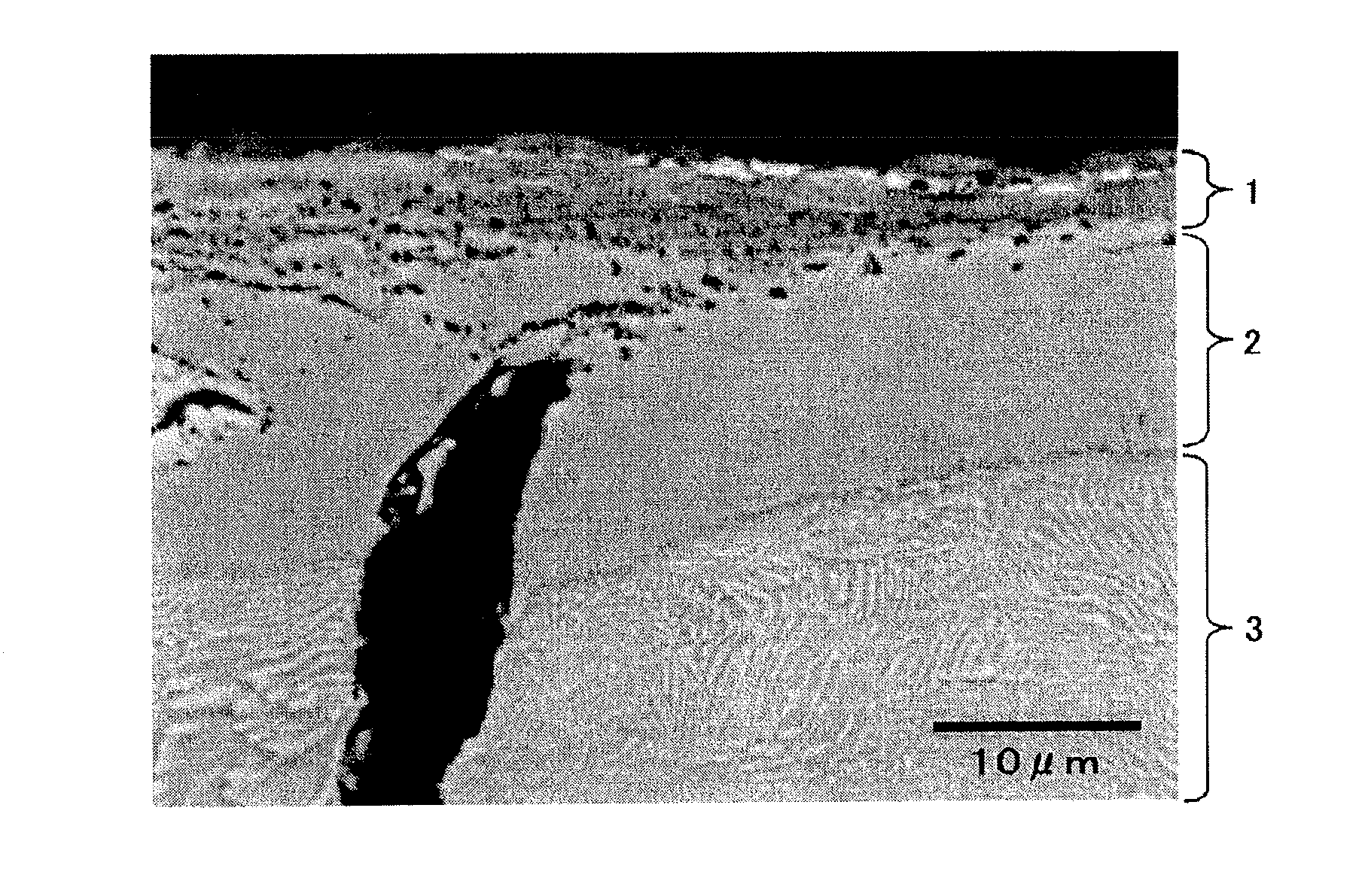
[0074]The cast-iron material (equivalent to FC200) was used as the material to cast a vehicular disc brake rotor having a diameter of 355 mm and a thickness of 32 mm and unnecessary parts (sprue, burr and the like) were removed. Then, the obtained vehicular disc brake rotor was subject to the heating treatment at 680° C. Then, a surface of the vehicular disc brake rotor was subject to the cutting work and was degreased by an alcohol-based cleaning agent.

[0075]After that, the vehicular disc brake rotor was put into a gas nitrocarburizing furnace (Fujikoshi Corp., EQ-6S type) and the nitrocarburizing treatment was then performed in which the treatment temperature was set to be 570° C. (controlling range: 565° C. to 575° C.) and the holding time at the treatment temperature was set to be 100 minutes (controlling range: 95 minutes to 105 minutes). At this time, ammonia of 5.0 m3 / h (controlling range: 4.5 m3 / h to 5.5 m3 / h) was used as the nitrogen supply source and methanol of 0.05 L / h (...

example 2

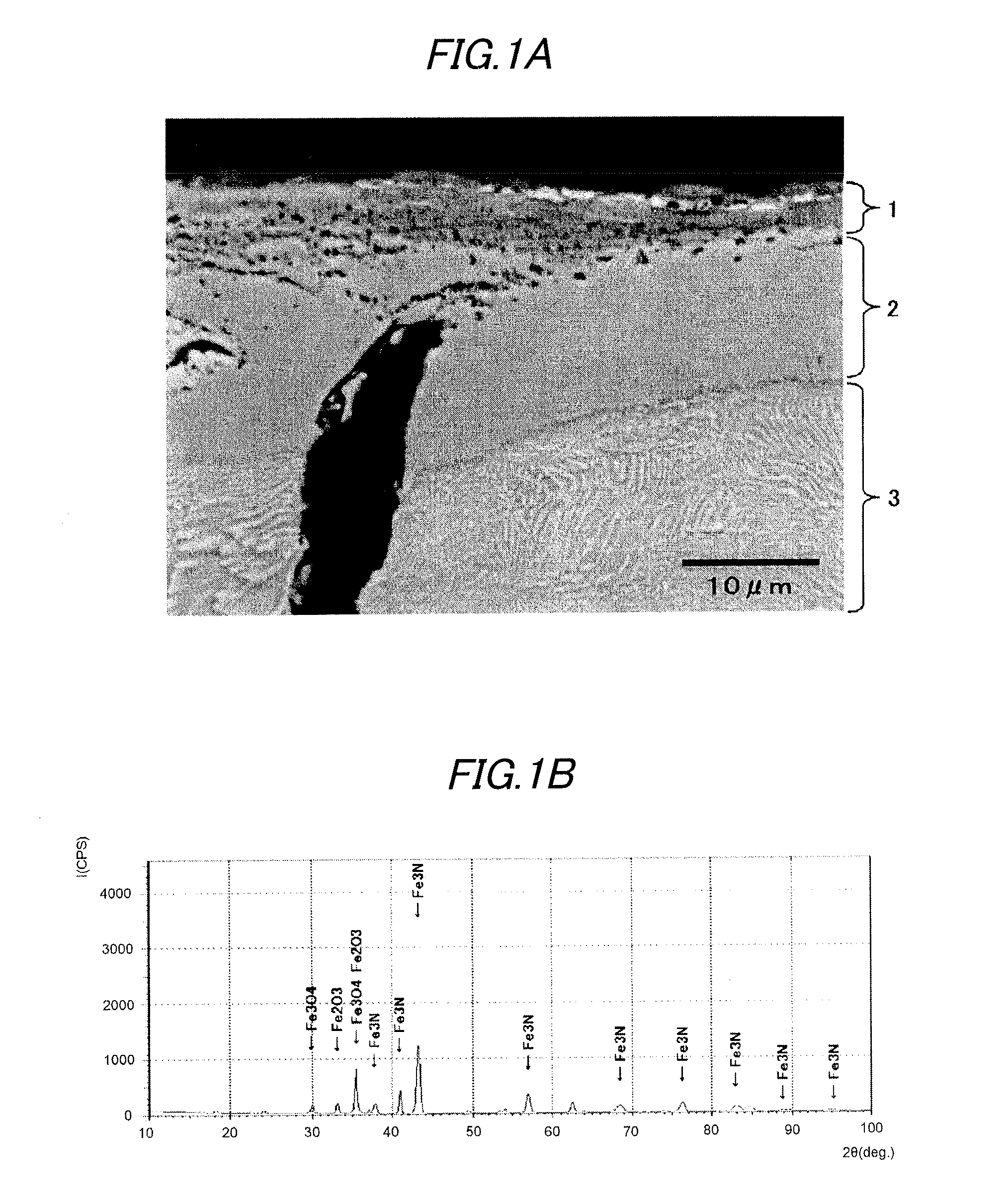
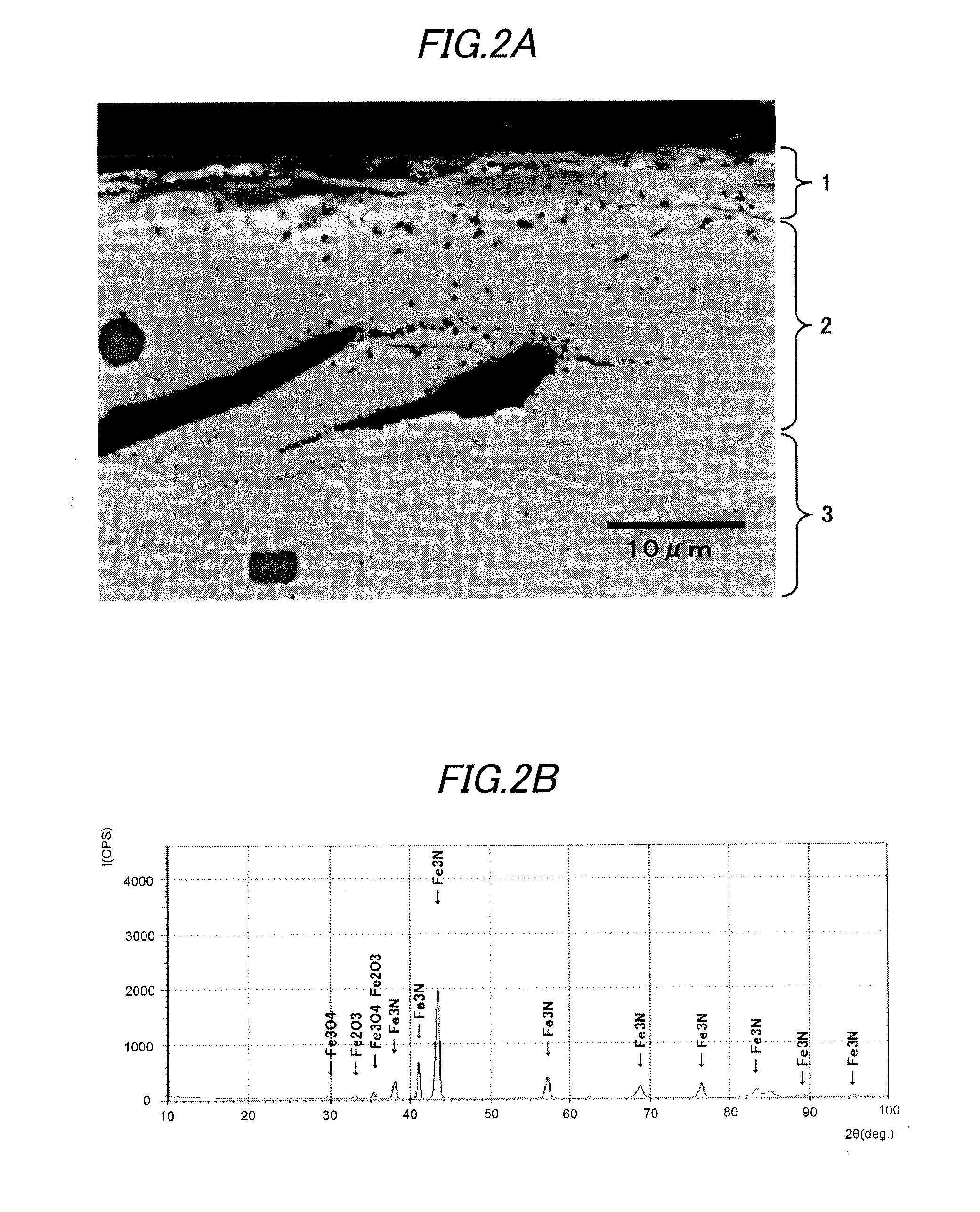
[0081]A vehicular disc brake rotor was obtained by the same method as the example 1, except that the rotor was taken out from the furnace and thus exposed to the atmosphere when the atmosphere temperature became 400° C. after the nitrocarburizing treatment. Like the example 1, the SEM observation, the X-ray diffraction analysis and the thickness measurement of the respective layers were performed for the vehicular disc brake rotor. As a result, it was confirmed that a nitrogen compound layer 2 having a thickness of 15 μm was formed on a nitrogen diffusion layer 3 having a thickness of 150 μm and a uniform and compact iron oxide layer 1 having Fe3O4 as a main component and having a thickness of 4 μm was formed on the nitrogen compound layer 2. The results are shown in FIGS. 2A and 2B.

[0082]After that, like the example 1, the surface images and binarization-processed images of the vehicular disc brake rotor were obtained and the pore area ratio (an average value of 25 views) of the su...

example 3

[0084]A vehicular disc brake rotor was obtained by the same method as the example 1, except that the rotor was taken out from the furnace and thus exposed to the atmosphere when the atmosphere temperature became 480° C. after the nitrocarburizing treatment. Like the example 1, the SEM observation, the X-ray diffraction analysis and the thickness measurement of the respective layers were performed for the vehicular disc brake rotor. As a result, it was confirmed that a nitrogen compound layer 2 having a thickness of 15 μm was formed on a nitrogen diffusion layer 3 having a thickness of 150 μm and a uniform and compact iron oxide layer 1 having Fe3O4 as a main component and having a thickness of 4 μm was formed on the nitrogen compound layer 2. The results are shown in FIGS. 3A and 3B.

[0085]After that, like the example 1, the surface images and binarization-processed images of the vehicular disc brake rotor were obtained and the pore area ratio (an average value of 25 views) of the su...


PUM

PropertyMeasurementUnit
temperatureaaaaaaaaaa
frictional coefficientaaaaaaaaaa
thicknessaaaaaaaaaa

Abstract

A vehicular disc brake rotor is provided with a cast-iron base, a nitrogen diffusion layer formed on the cast-iron base, a nitrogen compound layer formed on the nitrogen diffusion layer, and an iron oxide layer including Fe3O4 and formed on the nitrogen compound layer. In a burnish and a first re-burnish of a “Passenger car-Braking device-Dynamometer test procedures” (which is based on JASO C 406:2000), a change ratio of a frictional coefficient between the burnish and the first re-burnish is 10% or less.

Description

BACKGROUND OF THE INVENTION[0001]1. Field of the Invention[0002]The invention relates to a method of manufacturing a cast-iron vehicular disc brake rotor.[0003]2. Related Art[0004]A frictional surface of a cast-iron friction member that is used for a sliding part such as a vehicular disc brake rotor, a brake drum, a machine tool and the like is required to have high corrosion resistance and high wear resistance. Therefore, the surface of the cast-iron friction member has been coated with a coating film or zinc phosphate coating. However, the coating film or the coating is worn or delaminated over long time, so that it is difficult to secure the sufficient corrosion resistance and wear resistance.[0005]Compared to the above, a technology of performing a nitrocarburizing treatment for the frictional surface of the cast-iron friction member has been studied and utilized. The nitrocarburizing treatment is a surface treatment of enabling interstitial diffusion of nitrogen and carbon at t...

Claims


Application Information

Patent Timeline
Patent Type & Authority Applications(United States)
IPC IPC(8): F16D65/12
CPCF16D65/125F16D65/127C23C8/30C23C8/32C23C8/80
Inventor SUGAI, YOSHIYUKISEKI, KATSUJITAKADA, TAKUYA
Owner AKEBONO BRAKE IND CO LTD
Why Eureka
Try Eureka