Hard film, hard film formed body, and rolling bearing

a technology of hard film and body, applied in the direction of mechanical equipment, superimposed coating process, transportation and packaging, etc., can solve the problems of dlc film, low adhesiveness to a base material, prone to peeling, etc., and achieve excellent peeling resistance, high contact stress, excellent peeling resistance

Active Publication Date: 2014-08-07
NTN CORP
View PDF11 Cites 8 Cited by
  • Summary
  • Abstract
  • Description
  • Claims
  • Application Information

AI Technical Summary

Benefits of technology

[0037]As described above, the hard film of the present invention has the structure composed of (1) the first mixed layer (ratio between compositions is gradient), consisting of the Cr and the WC, which is formed directly on the base material, (2) the second mixed layer (ratio between compositions is gradient) consisting of the WC and the DLC, and (3) the surface layer consisting of the DLC. Because the first mixed layer formed directly on the base material contains the Cr, the first mixed layer is compatible with the iron-based material and superior to the first mixed layer containing Al, W or the like in the adhesiveness thereof to the base material. In the above-described structure, the WC has the hardness and the modulus of elasticity intermediate between that of the Cr and that of the DLC. Thus by forming the first mixed layer and the second mixed layer as the composition ratio-gradient layer containing the Wc, the concentration of the residual stress hardly occurs after the hard film is formed. Because the first mixed layer and the second mixed layer are formed as the composition ratio-gradient layer, the different materials thereof are physically connected to each other. In addition, the content of hydrogen in the second mixed layer is set to 10 to 45 atomic percent. Thus, even though the hard film is formed at a portion to be subjected to a high contact stress, the hard film can be prevented from peeling off the base material over a long period of time.
[0038]The above-described structure allows the hard film of the present invention to be excellent in its peeling resistance, even though it is formed at a portion to be subjected to a high contact stress and thus allows the DLC film to display its intrinsic property. Consequently the hard film formed body of the present invention can be utilized for various uses as a member excellent in its wear resistance, corrosion resistance, and fretting resistance.
[0039]In the rolling bearing of the present invention, because the hard film having the above-described structure is formed on the bearing member made of the iron-based material, the hard film can be prevented from peeling off the raceway surface and the rolling contact surface to be subjected to a high contact stress and the sliding contact surface of the cage to be subjected to a strong impact force over a long period of time. In addition, the hard film having the above-described structure is excellent in its resistance to the peeling resistance, although the hard film is formed on curved surfaces such as the raceway surfaces of the inner and outer rings and the rolling contact surfaces of the rolling elements and the nonplanar sliding contact surface of the cage. Consequently the rolling bearing of the present invention is excellent in its resistance to seizing, wear, and corrosion. Thus the raceway surfaces and the sliding contact surface of the cage are little damaged and have a long life, even though they are subjected to a severe lubrication state.

Problems solved by technology

Thus the DLC film has disadvantages that it is low in its adhesiveness to a base material and liable to peel therefrom.
Because the DLC film has the disadvantages that it is liable to peel off the base material, in forming the DLC film on the above-described surfaces of the bearing members of the rolling bearing, it is necessary to improve its adhesiveness to the surfaces of the bearing members.

Method used


Image

  • Hard film, hard film formed body, and rolling bearing
  • Hard film, hard film formed body, and rolling bearing
  • Hard film, hard film formed body, and rolling bearing

Examples


examples

Formation of Film on Inner and Outer Rings

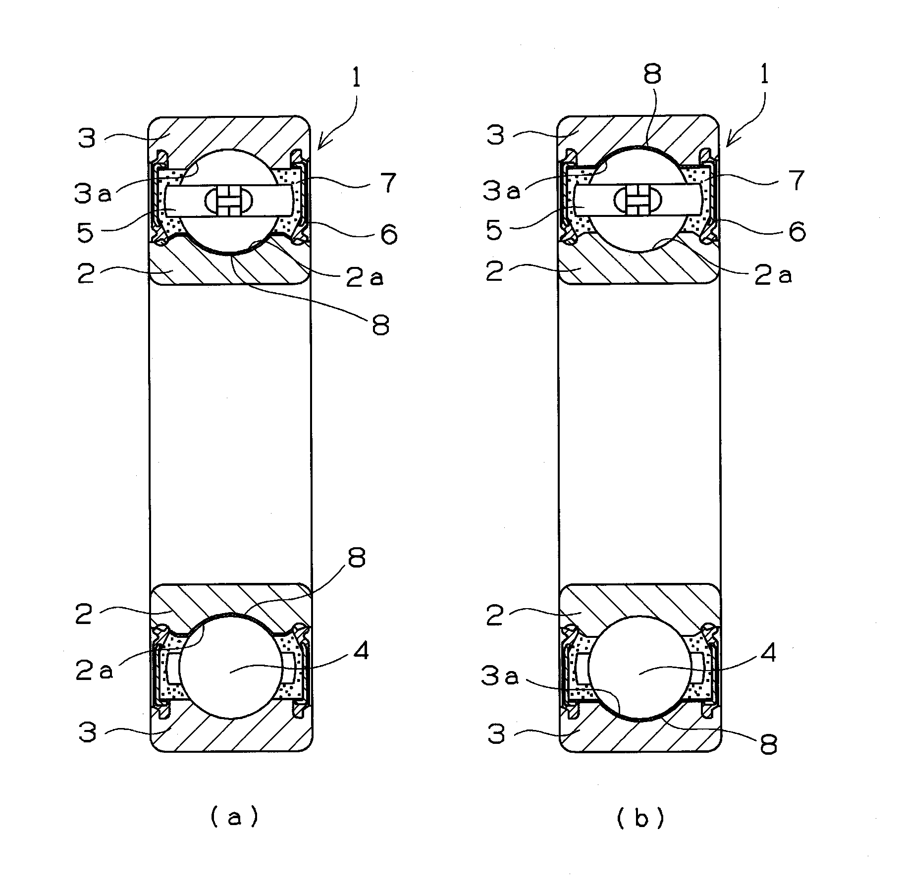
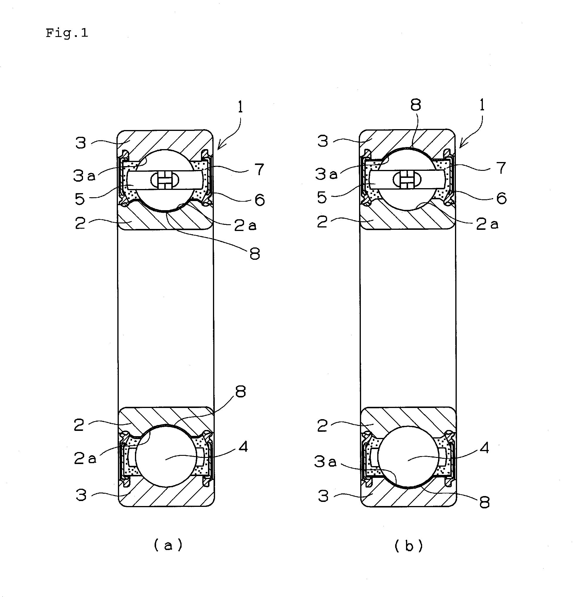
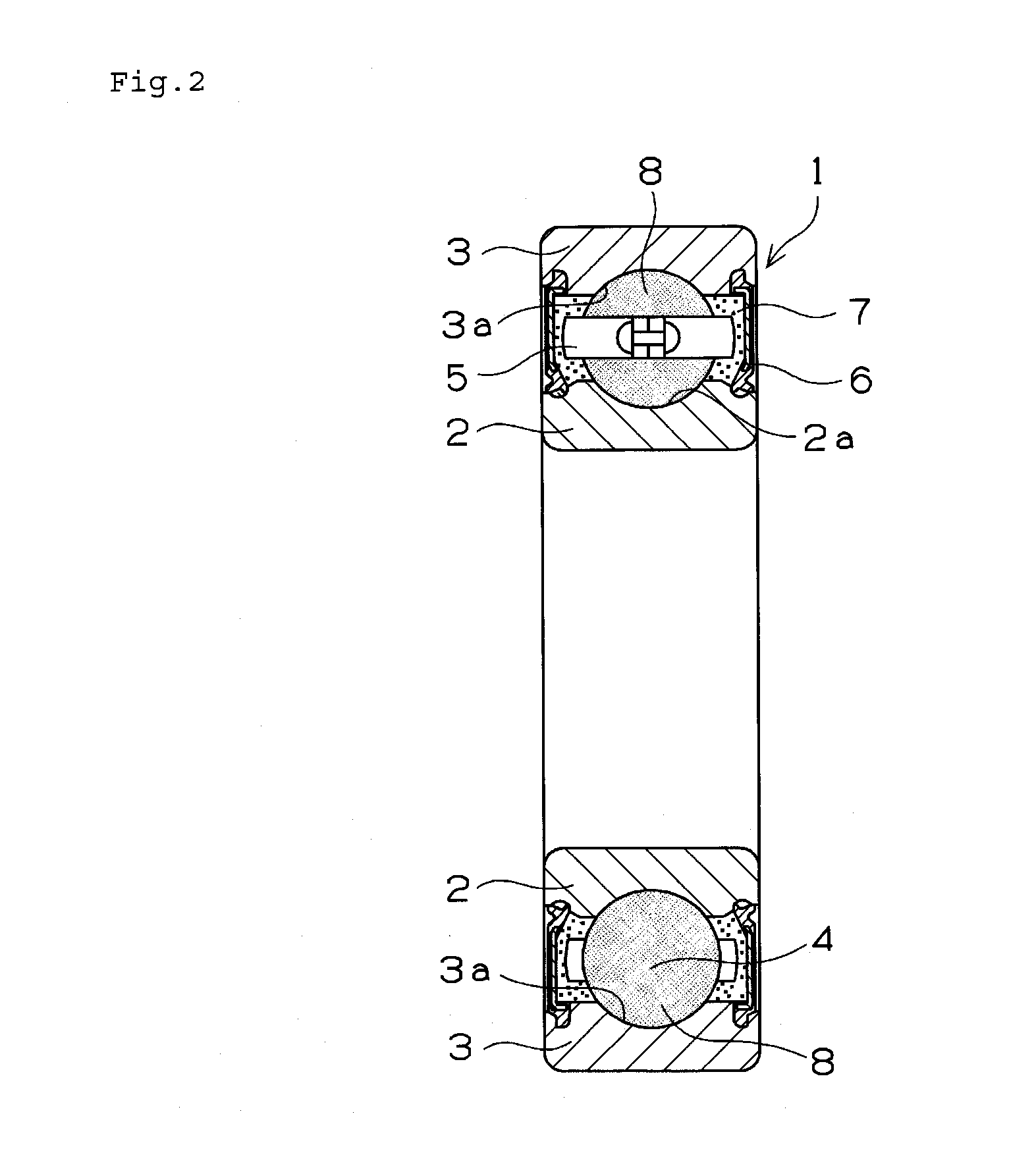
[0102]The hard films of the present invention were formed on predetermined base materials to evaluate the properties of the hard films. Similar hard films were formed on the raceway surfaces of inner rings of rolling bearings and the raceway surfaces of outer rings thereof to evaluate the properties of the rolling bearings.

[0103]The base materials used to evaluate the hard films, the UBMS apparatus, and the sputtering gas are as described below.

[0104](1) Base materials: shown in tables.

[0105](2) Dimensions of base materials: disks (φ48 mm×φ8 mm×7 mm, films were formed on plane surfaces) having surface roughnesses shown in the tables.

[0106](3) UBMS apparatus: UBMS202 / AIP composite apparatus produced by Kobe Steel, Ltd.

[0107](4) Sputtering gas: Ar gas

[0108]The condition of forming the first mixed layer (foundation layer of hard film) is described below. The inside of a film-forming chamber was vacuumed to about 5×10⁻³ Pa, and the base material...

examples a1 through a10

, A12, Comparative Examples A1 through A7, and Reference Examples A1 through A9

[0112]After the base materials shown in tables 1 through 3 were ultrasonically cleaned with acetone, the base materials were dried. After they were dried, they were mounted on the UBMS / AIP composite apparatus to form the first mixed layer and the second mixed layer both made of the materials shown in the tables in the above-described film-forming condition. The DLC film was formed on the second mixed layer as the surface layer in the film-forming conditions shown in the tables to obtain specimens each having a hard film. “Vacuum degree” shown in the tables means a vacuum degree inside the film-forming chamber of the above-described apparatus. The obtained specimens were subjected to a wear test, a hardness test, a film thickness test, a scratch test, and a thrust type rolling fatigue test (except reference examples). Results are shown in the tables. Reference numerals 1) through 7) shown below the table 1...

example a11

[0113]After base material (Vickers hardness of Hv 1000) subjected to plasma nitriding treatment by using a radical nitriding apparatus produced by Japan Electronics Industry Co., Ltd was ultrasonically cleaned with acetone, the base material was dried. After it was dried, it was mounted on the UBMS / AIP composite apparatus to form the first mixed layer (Cr / WC) and the second mixed layer (WC / DLC) both made of the materials shown in the table 1 in the above-described film-forming condition. The DLC film was formed on the second mixed layer as the surface layer in the film-forming condition shown in the table 1 to obtain a specimen having a hard film. The obtained specimen was subjected to tests similar to those conducted on the specimen of the example A1. Results are shown in the table 1.

[0114]A friction test was conducted on the obtained specimens by using a friction testing machine shown in FIG. 8. FIGS. 8 (a) and 8(b) show a front view and a side view respectively. A mating material...


PUM

PropertyMeasurementUnit
surface roughness Raaaaaaaaaaa
bias voltageaaaaaaaaaa
thicknessaaaaaaaaaa

Abstract

The present invention provides a hard film which has high wear resistance and excellent peeling resistance and can be prevented from peeling off a base material over a long period of time and a hard film formed body on which the hard film is formed. A hard film (8) has a structure composed of a first mixed layer (8a), consisting mainly of Cr and WC, which is formed directly on a raceway surface (2a) of an inner ring (2) (base material) of a rolling bearing, a second mixed layer (8b), consisting mainly of WC and DLC, which is formed on the first mixed layer (8a), and a surface layer (8c), consisting mainly of DLC, which is formed on the second mixed layer (8b). In the first mixed layer (8a), a content rate of the Cr becomes continuously or stepwise lower and that of the DLC becomes continuously or stepwise higher from a side of the base material toward a side of the second mixed layer (8b). In the second mixed layer (8b), a content rate of the WC becomes continuously or stepwise lower and that of the DLC becomes continuously or stepwise higher from a side of the first mixed layer (8a) toward a side of the surface layer (8c). A content of hydrogen in the second mixed layer (8b) is set to 10 to 45 atomic percent.

Description

TECHNICAL FIELD[0001]The present invention relates to a hard film, excellent in its wear resistance and peeling resistance, which is formed on members such as sliding members, car parts, molding dies consisting of an iron-based base material and a superhard material and a hard film formed body on which the hard film is formed. More particularly the present invention relates to a rolling bearing in which the hard film is formed on a raceway surface of an inner ring, a raceway surface of an outer ring, a surface of a rolling element, and a sliding contact surface of a cage.BACKGROUND ART[0002]A hard carbon film is a hard film called diamond-like carbon (hereinafter referred to as DLC. Film / layer consisting mainly of DLC is also called DLC film / layer). Various naming is given to the hard carbon. For example, it is called a hard amorphous carbon, amorphous carbon, hard amorphous-type carbon, i-carbon, and diamond-shaped carbon. These terms are not clearly distinguished from one another....

Claims


Application Information

Patent Timeline
Patent Type & Authority Applications(United States)
IPC IPC(8): F16C33/62F16C33/34F16C33/56F16C33/32F16C33/66F16C33/64
CPCF16C33/62F16C33/6603F16C33/64F16C33/565F16C33/32F16C33/34F16C2223/14F16C2204/66F16C2204/44F16C2206/04F16C2206/58F16C2206/82F16C2223/30F16C2202/04C23C14/024C23C14/027C23C14/0605C23C14/3464C23C28/324C23C28/341C23C28/343C23C28/347C23C28/36Y10T428/2495Y10T428/30
Inventor TSUTSUI, HIDEYUKIOOHIRA, KOUYANAKANISHI, MASAKI
Owner NTN CORP
Why Eureka
Try Eureka