Inner-cooling transformer rolling iron core

A technology of wound iron core and transformer, which is applied in the field of wound iron core transformer and three-dimensional transformer wound iron core structure, which can solve the problems of unsatisfactory cooling effect, difficult temperature reduction, easy deformation of iron core, etc. Heat dissipation effect, overcoming the difficulty of cooling, and eliminating the effect of the hottest point

Active Publication Date: 2013-04-17
马志刚
View PDF6 Cites 5 Cited by
  • Summary
  • Abstract
  • Description
  • Claims
  • Application Information

AI Technical Summary

Problems solved by technology

The advent of coiled iron cores, especially the advent of three-dimensional coiled iron cores, provides a new direction for the development of a new generation of power transformers. It has obvious advantages over traditional iron cores, especially in terms of energy saving and environmental protection. However, there is still a high-temperature core area inside the iron core, and its temperature is difficult to reduce. The technology is still immature and needs further development
[0003] Chinese invention patent CN201110139988.6 discloses an amorphous alloy dry-type transformer with a non-encapsulated three-dimensional wound core. The cooling effect of the column structure is not ideal, and the inner ring of the existing iron core is a rectangular longitudinal section. When it is wound outside, the four corners are approximately circular. The section of the iron core column is rectangular, stepped or polygonal, which is very True circular, the internal stress of this frame-type wound core element is extremely uneven between the joint between its yoke and vertical core, which causes the core to be easily deformed in a strong electromagnetic field

Method used


Image

  • Inner-cooling transformer rolling iron core
  • Inner-cooling transformer rolling iron core
  • Inner-cooling transformer rolling iron core

Examples


Embodiment Construction

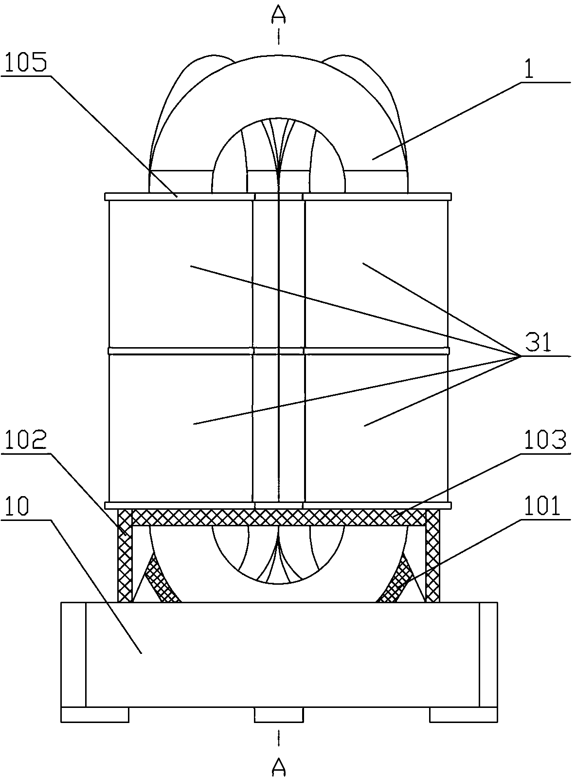
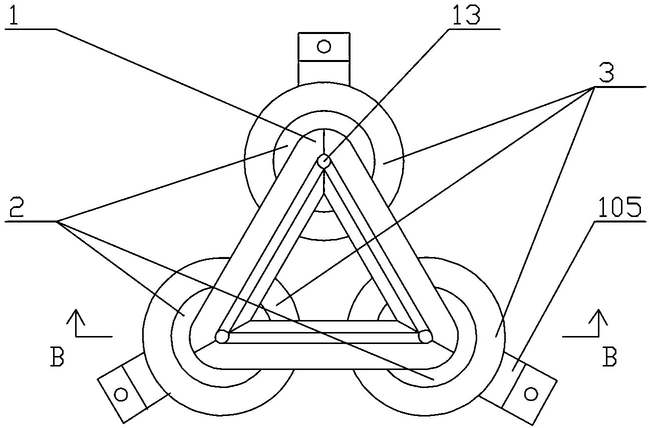
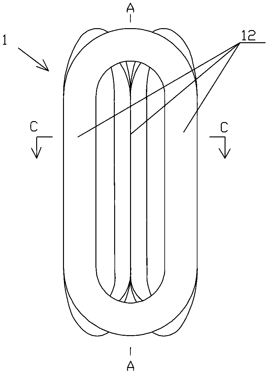
[0021] Figure 1-7 It is a figure which shows each embodiment of the inner cooling type transformer wound core of this invention. The specific embodiments of the present invention will be described in further detail below in conjunction with the accompanying drawings, but this does not constitute any limitation to the present invention.

[0022] figure 1 It is a partial structural schematic diagram of an embodiment of an inner-cooled transformer wound core of the present invention, figure 2 yes figure 1 , which shows the overall appearance structure of the inner-cooled three-dimensional wound iron core 1 fitted with low-voltage and high-voltage windings. see Figure 1 to Figure 2 , the novel inner-cooled three-dimensional wound iron core power transformer of the present invention comprises a three-dimensional wound iron core 1 of a three-phase three-column three-dimensional structure, and its three identical iron core columns 12 have such figure 1 As shown in the paralle...


PUM


Abstract

An inner-cooling transformer rolling iron core is formed by three rolling iron core components with closed magnetic circuits. Each rolling iron core component comprises two straight line portions and two arc portions. Each closed magnetic circuit is formed by connecting the two straight line portions and the two arc portions of each rolling iron core component in end-to-end mode. A vertical section of each closed magnetic circuit is in a shape of an athletic track, every two of six straight line portions of the three rolling iron core components are combined with each other to form three iron core columns of the rolling iron core, and six arc portions of the three rolling iron core components form six arc iron yokes connecting the three iron columns and arranged on the upper portion and the lower portion. Two straight line portions of each rolling iron core component are provided with cooling grooves extending along the central lines of the rolling iron core component respectively, every two groove openings of the two cooling grooves on two adjacent rolling iron core components are clamped oppositely, and an inner cooling channel penetrating vertically is formed inside each iron core column. The inner-cooling transformer rolling iron core adopts a novel three-dimensional rolling iron core structure and new design of removing an innermost hot point of the rolling iron core so that the temperature of the rolling iron core is reduced, and the service life of the rolling iron core is prolonged.

Description

technical field [0001] The invention relates to a winding core type transformer, in particular to a three-dimensional transformer winding core structure with internal cooling passages, and belongs to the technical field of power transformer manufacturing. Background technique [0002] The transformer is an important electrical appliance widely used in the power distribution system. It completes the economical transmission, distribution and safe use of electric power by increasing or reducing the voltage. With the rapid development of the electrical industry, the functional requirements such as voltage and capacity of power transformers and the performance requirements of no-load, temperature rise, insulation, and life are getting higher and higher, and the core of improving functions and performances is One of the technologies lies in the iron core of the transformer. Iron cores can be divided into laminated iron cores and wound iron cores (referred to as coiled iron cores)...

Claims


Application Information

Patent Timeline
Patent Type & Authority Applications(China)
IPC IPC(8): H01F27/26H01F27/245H01F27/08H01F27/30
Inventor 马志刚
Owner 马志刚
Why Eureka
Try Eureka