
Eureka
For R&D, Eureka makes reading and utilizing patents & technical documents easy.
Eureka AIR
Designed for self-driven R&D workflows. Generate viable solutions, solve complex R&D challenges, empower your innovation with AI.

Eureka Materials
Designed for material experts only. Revolutionize your material R&D, from search, analyze, to developing new materials.

TechResearch
Generate reliable direction feasibility study reports for your R&D in just a few steps.

TechSeek
Discover and master advanced knowledge NOW. Basics, ideas, possibilities, all at once.

TechMind
As an expert in R&D Theories, TechMind can generates customized viable solutions instantly.

TechRisk
Analyze your overall solution with one click, know your potential R&D risks in advance.

TechMonitor
Get weekly tech updates, stay abreast of the latest tech innovations and key insights.
High-gain high-efficiency flat plate antenna loaded with left-handed material
A left-handed material, flat-panel antenna technology, used in antennas, slot antennas, resonant antennas, etc., can solve the problems of high gain, complex design and debugging, small size, etc., and achieve the effect of high gain, compact structure, and large bandwidth
- Summary
- Abstract
- Description
- Claims
- Application Information
AI Technical Summary
Problems solved by technology
Method used
Image

Examples
Embodiment 1
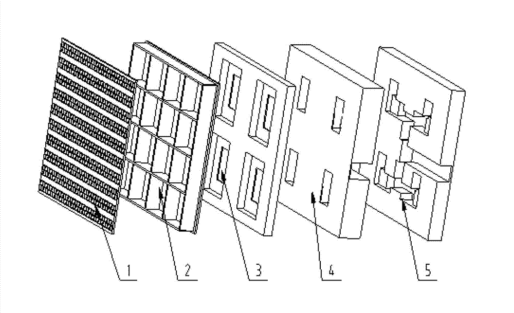
[0035] A high-gain and high-efficiency planar antenna loaded with left-handed materials, including a feed layer 5, a coupling layer 4, a resonant cavity layer 3, and a radiation layer 2 arranged in sequence according to the propagation direction of electromagnetic waves; the left-handed material is arranged on the radiation layer Dielectric board 1.
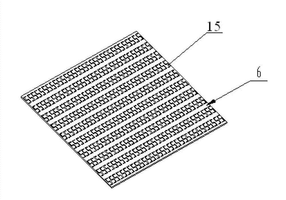
[0036]The dielectric plate 1 loaded with left-handed materials includes a dielectric plate 6 with a dielectric constant of 2.68, and a metal patch 15 in the shape of a seven-segment number "5" is arranged on the dielectric plate 6; the adjacent metal patch 15 The longitudinal spacing is SL=7.65mm, the lateral spacing of the adjacent metal patches 15 is SW=2.75mm; the length of the metal patches 15 is ML=4.7mm, and the width of the metal patches 15 is MW=2mm; The thickness of the metal patch 15 is d=1mm; the metal patch 15 is arranged on the dielectric board 6 in an arrangement of 10 rows×32 columns. The metal patch 15 is a coppe...
Embodiment 2
[0038] A high-gain and high-efficiency planar antenna loaded with left-handed materials as described in Example 1, the difference is that
[0039] The radiation layer 2 includes a plurality of radiation units, and each radiation unit includes a grid radiator 7, and each grid radiator 7 includes four rectangular grid side walls surrounded by side walls and a grid bottom, Radiation slots 8 are arranged on the grid bottom.
[0040] The inner length L=20mm, inner width W=20mm, inner height H=8mm, and grid bottom thickness h=1mm of each grid radiator 7; the length FL=12mm and width FW= 2mm.
[0041] Each radiation unit includes 16 grid radiators 7, and the 16 grid radiators 7 are arranged on the radiation layer 2 in an arrangement of 4 rows×4 columns.
[0042] The resonant cavity layer 3 includes a plurality of resonant cavity units, and each resonant cavity unit includes 4 resonant cavities 9, and the 4 resonant cavities 9 are arranged on the resonant cavity layer in an arrangem...
PUM
 Abstract
Description
Claims
Application Information
 - R&D Engineer
- R&D Manager
- IP Professional
- Industry Leading Data Capabilities
- Powerful AI technology
- Patent DNA Extraction
Browse by: Latest US Patents, China's latest patents, Technical Efficacy Thesaurus, Application Domain, Technology Topic, Popular Technical Reports.
© 2024 PatSnap. All rights reserved.Legal|Privacy policy|Modern Slavery Act Transparency Statement|Sitemap|About US| Contact US: help@patsnap.com