Surge protection circuit for signal circuit

A technology for protecting circuits and signal lines, applied to emergency protection circuit devices, emergency protection circuit devices for limiting overcurrent/overvoltage, circuit devices, etc. The protection circuit responds slowly, reduces the protection effect and other problems, and achieves the effect of improving the protection level, avoiding signal loss and reducing capacitance

Active Publication Date: 2013-04-17
SHENZHEN SUNLORD ELECTRONICS
View PDF5 Cites 8 Cited by
  • Summary
  • Abstract
  • Description
  • Claims
  • Application Information

AI Technical Summary

Problems solved by technology

[0003] The present invention provides a surge protection circuit for signal lines, which solves the problems of slow response of the first-level protection circuit, excessive peak residual voltage, poor cooperation between the first-level and second-level protection circuits, and reduced protection effect in the prior art. problem, and the problem that the protection circuit causes loss to the signal transmitted by the signal line

Method used


Image

  • Surge protection circuit for signal circuit
  • Surge protection circuit for signal circuit
  • Surge protection circuit for signal circuit

Examples


Embodiment 1

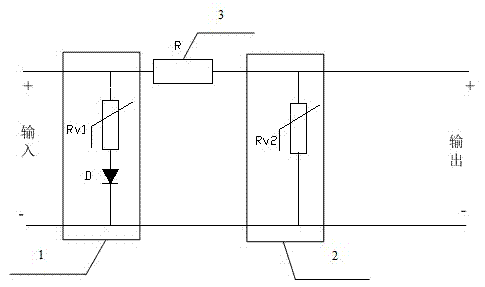
[0020] Such as image 3 As shown, the surge protection circuit for the signal line provided in this embodiment is as follows:

[0021] A surge protection circuit for signal lines, comprising a primary protection circuit 1, a secondary protection circuit 2 and a resistance element 3. Among them, the first-level protection circuit 1 and the second-level protection circuit 2 are connected in parallel with the protected circuit; the resistance element 3 is connected in series between the first-level protection circuit 1 and the second-level protection circuit 2, which can limit the surge current in the first-level protection circuit 1 Too much flows into the secondary protection circuit 2, thereby forming a well-coordinated primary and secondary protection circuit.

[0022] The above-mentioned primary protection circuit 1 includes a varistor Rv1 and a diode D, and the varistor Rv1 is connected in series with the diode D, which reduces the capacitance of the primary protection cir...

Embodiment 2

[0029] Such as Figure 4 As shown, the surge protection circuit for the signal line provided in this embodiment is as follows:

[0030] Compared with the protection circuit provided in Embodiment 1, the diode D is replaced by a magnetic bead L in the signal line surge protection circuit provided in this embodiment.

[0031] A surge protection circuit for signal lines includes a primary protection circuit 4 , a secondary protection circuit 2 and a resistance element 3 . Among them, the first-level protection circuit 4 and the second-level protection circuit 2 are connected in parallel with the protected circuit; the resistance element 3 is connected in series between the first-level protection circuit 4 and the second-level protection circuit 2, which can limit the surge current in the first-level protection circuit 4 Too much flows into the secondary protection circuit 2, thereby forming a well-coordinated primary and secondary protection circuit.

[0032] The primary protec...

Embodiment 3

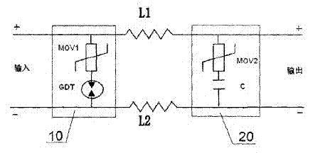
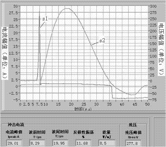
[0039] The circuit structure of this embodiment is the same as Embodiment 1, as image 3As shown, in this embodiment, the DC operating voltage of the varistor Rv1 of the primary protection circuit 1 is 9V, the breakdown voltage is 14V, and the diode D is a rectifier diode. The current change curve S2 and the voltage change curve S2 after the protection circuit 1 discharges are as follows: Figure 5 As shown, the residual voltage peak value after discharge is 16.56V; when the diode D in the primary protection circuit 1 above is replaced by a gas discharge tube with a DC breakdown voltage of 270V and other parameters remain unchanged, the waveform diagram Such as figure 2 As shown, the peak residual voltage generated by it is 277.8V. It can be seen that the use of diodes and varistors in series in the primary protection circuit can effectively absorb surges, greatly reduce the peak value of residual voltage, and protect the circuit efficiently.


PUM


Abstract

The invention discloses a surge protection circuit for a signal circuit. The surge protection circuit for the signal circuit comprises a primary protection circuit, a secondary protection circuit and a resistor element. The primary protection circuit and the secondary protection circuit are connected in parallel with a protected circuit; the resistor element with low resistance is connected in series between the primary protection circuit and the secondary protection circuit. The primary protection circuit comprises a piezoresistor and a diode or a piezoresistor and a magnetic bead; the piezoresistor is connected in series with the diode or the magnetic bead; and the secondary protection circuit comprises a piezoresistor with low capacitance. Under a normal operation condition of a line, the primary protection circuit and the secondary protection circuit are in a high-impedance state, and thus, influence on signal transmission is small. When a surge peak is generated, a quick response is made by the primary protection circuit so as to discharge a surge in low-impedance state; surge current is further restrained by the resistor element so as to reduce the surge flowing into the secondary protection circuit; and a clamp voltage is further reduced by the piezoresistor in the secondary protection circuit, so that a protection level is improved.

Description

technical field [0001] The invention relates to an emergency protection circuit, in particular to a surge protection circuit for signal lines. Background technique [0002] A Chinese patent application document with publication number 102025141A discloses an anti-surge protection circuit, such as figure 1 As shown, the gas discharge tube is used in the primary protection circuit of the anti-surge protection circuit to discharge the surge, and the piezoresistor is connected in series with the gas discharge tube to solve the freewheeling problem of the gas discharge tube, but the response speed of the gas discharge tube itself Slower, the surge current will flow into the secondary protection circuit before the primary protection circuit responds, and a large residual voltage peak will appear, such as figure 2 As shown, the cooperation of the primary and secondary protection circuits creates a gap, which greatly reduces the protection strength. Varistors have the advantages ...

Claims


Application Information

Patent Timeline
Patent Type & Authority Applications(China)
IPC IPC(8): H02H9/04
Inventor 毛海波冯志刚贾广平杜士雄
Owner SHENZHEN SUNLORD ELECTRONICS
Why Eureka
Try Eureka