Surge protection circuit for signal circuit
A technology for protecting circuits and signal lines, applied to emergency protection circuit devices, emergency protection circuit devices for limiting overcurrent/overvoltage, circuit devices, etc. The protection circuit responds slowly, the residual voltage peak is too large, etc., to improve the protection level, avoid signal loss, and respond quickly
- Summary
- Abstract
- Description
- Claims
- Application Information
AI Technical Summary
Problems solved by technology
Method used
Image
Examples
Embodiment 1
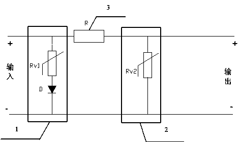
[0020] Such as image 3 As shown, the surge protection circuit for signal lines provided by this embodiment is as follows:
[0021] A surge protection circuit for signal lines includes a primary protection circuit 1, a secondary protection circuit 2 and a resistance element 3. Among them, the primary protection circuit 1 and the secondary protection circuit 2 are connected in parallel with the protected circuit; the resistance element 3 is connected in series between the primary protection circuit 1 and the secondary protection circuit 2, which can limit the surge current in the primary protection circuit 1. Too much flows into the secondary protection circuit 2, thereby forming a well-coordinated primary and secondary protection circuit.
[0022] The above-mentioned primary protection circuit 1 includes a varistor Rv1 and a diode D. The varistor Rv1 is connected in series with the diode D, which reduces the capacitance of the primary protection circuit 1, increases the impedance, ...
Embodiment 2
[0029] Such as Figure 4 As shown, the surge protection circuit for signal lines provided by this embodiment is as follows:
[0030] Compared with the protection circuit provided in the first embodiment, the surge protection circuit for the signal line provided in this embodiment changes the diode D to a magnetic bead L.
[0031] A surge protection circuit for signal lines includes a primary protection circuit 4, a secondary protection circuit 2 and a resistance element 3. Among them, the primary protection circuit 4 and the secondary protection circuit 2 are connected in parallel with the protected circuit; the resistance element 3 is connected in series between the primary protection circuit 4 and the secondary protection circuit 2 to limit the surge current in the primary protection circuit 4 Too much flows into the secondary protection circuit 2, thereby forming a well-coordinated primary and secondary protection circuit.
[0032] The above-mentioned primary protection circuit 4...
Embodiment 3
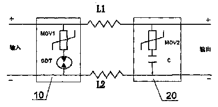
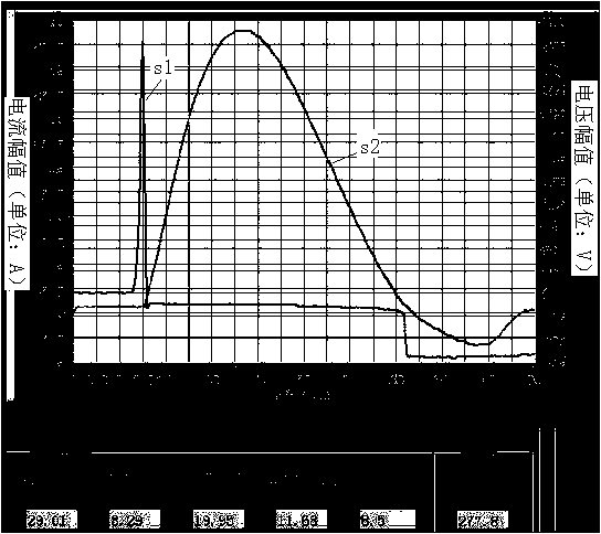
[0039] The circuit structure of this embodiment is the same as that of embodiment 1, such as image 3 As shown, in this embodiment, the DC working voltage of the varistor Rv1 of the primary protection circuit 1 is 9V, the breakdown voltage is 14V, and the diode D uses a rectifier diode. Under the 8 / 20μs waveform and 29A impulse current, it passes through the primary The current change curve S2 and voltage change curve S2 after the discharge of the protection circuit 1 are as Figure 5 As shown, the peak value of the residual voltage after discharge is 16.56V; when the diode D in the first-level protection circuit 1 is replaced with a gas discharge tube with a DC breakdown voltage of 270V and the other parameters remain unchanged, the waveform diagram Such as figure 2 As shown, the peak residual voltage generated by it is 277.8V. It can be seen that the use of diodes and varistors in series in the primary protection circuit can effectively absorb surges, greatly reduce the resi...
PUM
 Abstract
Description
Claims
Application Information
 - R&D
- Intellectual Property
- Life Sciences
- Materials
- Tech Scout
- Unparalleled Data Quality
- Higher Quality Content
- 60% Fewer Hallucinations
Browse by: Latest US Patents, China's latest patents, Technical Efficacy Thesaurus, Application Domain, Technology Topic, Popular Technical Reports.
© 2025 PatSnap. All rights reserved.Legal|Privacy policy|Modern Slavery Act Transparency Statement|Sitemap|About US| Contact US: help@patsnap.com


