Brushless direct current motor electronic speed governor based on STM32

An electronic governor and circuit technology, applied in the field of model aircraft, can solve problems such as unfavorable governor expansion, larger space occupied by hardware, and weak anti-interference ability, so as to improve control performance, use function, stability and The effect of improving real-time performance and enhancing anti-interference ability

Inactive Publication Date: 2013-04-17
GUANGXI NORMAL UNIV
3 Cites 19 Cited by

AI-Extracted Technical Summary

Problems solved by technology

[0002] In various aircraft models, the electronic governor is an important part of the aircraft model. It is mainly used to receive the control command signal of the aircraft model and adjust the speed according to the signal. The commonly used rotor position detection method of the existing sensorless brushless DC motor is The counter electromotive force zero-crossing detection method usually uses an electronic governor for detection. In the traditional electronic governor of aeromodelling, the controller basically uses a single-chip microcomputer. The running speed is not very high, and its counter electromotive force zero-crossing detection method is usually to use a voltage comparator to directly ...

Method used

TIM1_CC4 event is arranged on the PWM high level interval that is used to drive and takes place, and counter electromotive force zero-crossing signal just carries out synchronous detection in PWM high level interval like this, and detection accuracy is relevant with PWM frequency, suitably improves PWM frequency and just can improve detection Accuracy, in the present invention, the frequency of TIM1 advanced timer is set as 60kHz.
The present invention makes full use of the AD rule group of STM32 micro-controller and the mode that injection group combines, and AD rule group is used for the detection of supply voltage, electric current and temperature, has greatly improved the real-time property of monitoring, makes the protection ability of system It has been...

Abstract

The invention discloses a brushless direct current motor electronic speed governor based on STM32, and the speed governor comprises an STM32 micro controller, a power driving circuit, a three-phase inverter circuit, a voltage and current monitoring circuit, a communication module circuit, a counter electromotive force detection circuit, an indicator circuit and the like; the STM32 micro controller drives the three-phase inverter circuit through the power driving circuit through an H-PWM-L-ON method, carries out connection and three-phase and six-state control on a motor, and synchronously detects a counter electromotive force zero-crossing signal among high-level intervals of pulse width modulation (PWM); the voltage of a three-phase end is converted through an analog-digital (AD) injection group method in the STM32 micro controller; the counter electromotive force zero-crossing signal is acquired by comparing corresponding end voltage and central point voltage in software; the AD injection group conversion is triggered by a TIM1_CC4 event; the power voltage, current and temperature detection is converted through a continuous circulating scanning method of an AD rule group and sent to the corresponding random-access memories (RAMs) through a direct memory access (DMA) channel; and compared with an the electronic speed governor which adopts a single-chip microcomputer, the brushless direct current motor electronic speed governor based on STM32 has the characteristics of higher anti-interference capability, small hardware space, higher performance and a plurality of communication methods.

Application Domain

Technology Topic

Image

  • Brushless direct current motor electronic speed governor based on STM32
  • Brushless direct current motor electronic speed governor based on STM32
  • Brushless direct current motor electronic speed governor based on STM32

Examples

  • Experimental program(1)

Example Embodiment

[0018] The present invention will be further described below in conjunction with the drawings and embodiments.
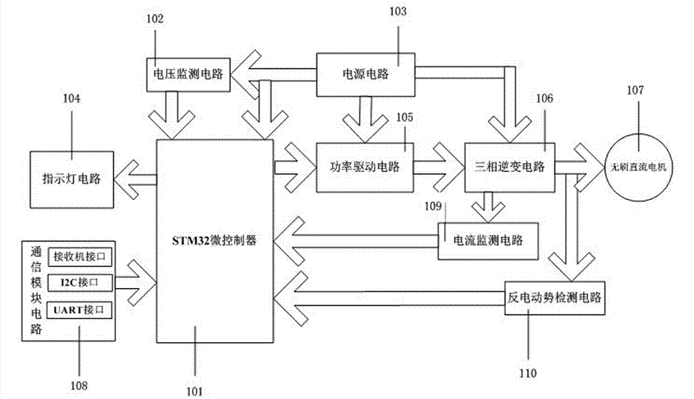
[0019] according to figure 1 Shown is a schematic structural diagram of an embodiment of the present invention, which consists of STM32 microcontroller 101, power drive circuit 105, three-phase inverter circuit 106, voltage monitoring circuit 102, current monitoring circuit 109, communication module circuit 108, and back-EMF detection circuit 110, indicator circuit 104 and power supply circuit 103, STM32 microcontroller 101 is connected to communication module circuit 108, power drive circuit 105, back electromotive force detection circuit 110, voltage monitoring circuit 102, current monitoring circuit 109 and indicator circuit 104, respectively The three-phase inverter circuit 106 is connected to the power drive circuit 105 and the brushless DC motor 107, and the power supply circuit 103 is connected to the STM32 microcontroller 101, the power drive circuit 105, and the three-phase inverter circuit 106.
[0020] in figure 2 As shown in the circuit schematic diagram of an embodiment of the present invention, the STM32 microcontroller 201 is the control core of the system. It controls the startup and closed-loop operation of the brushless DC motor, detects the zero-crossing signal of the back electromotive force, obtains the communication signal, and monitors the voltage in real time. , Current and temperature. The CH1, CH2, and CH3 ports of the TIM1 advanced timer of the STM32 microcontroller 201 are connected to the high-side control terminal HIN of the power drive circuit 205, and the PD9, PD10, and PD11 ports are respectively connected to the power drive circuit 205 The low-side control terminal LIN is connected with the H-PWM-L-ON method through the three-phase inverter circuit 206 to perform two-by-two conduction three-phase six-state control of the motor. In this embodiment, the STM32 microcontroller 201 uses STM32F103VBT6 .
[0021] The power drive circuit 205 is composed of three integrated drive chips. Each drive chip drives the upper and lower arm MOSFETs of each phase. The chip uses IR2101S. The power supply voltage of the drive chip is the same as the power supply voltage; the three-phase inverter circuit 206 is composed of six identical The N-channel MOSFET tube constitutes a bridge circuit to realize the six-step commutation control of the motor. In this embodiment, the N-channel MOSFET tube adopts IRF3205.
[0022] The communication module circuit 208 is composed of a receiver interface, an I2C interface and a UART interface. The receiver interface has a power line and a signal line. The signal line is connected to the TIM3 timer CH1 port of the STM32 microcontroller 201. The I2C interface and the UART interface are respectively It is led out by the PB6 and PB7 ports of the STM32 microcontroller 201 and the PD5 and PD6 ports, so that the communication module circuit 208 can automatically recognize the mode of the given signal, thereby realizing multiple communication modes.
[0023] The indicator circuit 204 is composed of a red LED light and a green LED light control circuit, which are respectively connected to the PC6 and PC7 ports of the STM32 microcontroller 201 through a current-limiting resistor. When the motor is running normally, starting failure, stalling, and excessive current Or when the temperature is too high, the corresponding LED lights produce different states.
[0024] The voltage monitoring circuit 202 is composed of a voltage divider circuit composed of resistors, which is connected to the ADC_IN5 port of the STM32 microcontroller 201, and is used to monitor the power supply voltage of the motor in real time. When the voltage is lower than the set voltage threshold, it will send out an indication signal, red LED The light is always on.
[0025] The current monitoring circuit 209 is connected to the three-phase inverter circuit 206 and connected to the ADC_IN4 port of the STM32 microcontroller 201. The current monitoring circuit 209 is used to detect the current in the motor circuit in real time. When the current is too large due to a stall, etc. The current monitoring circuit 209 turns off the motor 207 and the red LED light flashes five times.
[0026] The back-EMF detection circuit 210 is a voltage divider circuit composed of six resistors. It is connected to the ADC_IN1, ADC_IN2, and ADC_IN3 ports of the STM32 microcontroller 201, and the three-phase terminal voltage is reduced to make it consistent with the STM32 microcontroller 201 The AD conversion voltage range.
[0027] press image 3 As shown in the schematic diagram of the working flow of an embodiment of the present invention, when the program starts to run in S301, a series of initialization S302 is performed, including clock initialization, port configuration initialization, timer initialization, AD conversion initialization, DMA function initialization, and interrupt initialization. Among them, the rule group and injection group are set in the AD conversion initialization configuration. The detection of power supply voltage, current and temperature is converted in the continuous cycle scanning mode of the AD rule group, and sent to the corresponding RAM through the DMA channel, and the terminal voltage is converted in the AD injection group mode , And read the injection group conversion value in the interrupt.
[0028] After the initialization S302 is completed, if the communication signal S303 is received, the motor is started in the open loop S305 under the start command S304, and the motor is started by a three-stage start method, that is, the two phases are first turned on under the open loop, and the rotor is positioned. The external synchronization mode makes the motor gradually accelerate. When it accelerates to a state where the back-EMF signal S306 can be correctly detected, switch to the self-synchronization mode to make the motor enter the closed-loop operation S307 state. At this time, the motor speed is determined by the received communication signal PWM The duty cycle is adjusted.
[0029] Perform back-EMF zero-crossing signal detection S308 during the closed-loop operation of the motor S307. If the back-EMF zero-crossing signal is not detected within the preset time, perform forced commutation S309 on the motor and determine whether the motor is blocked. If a stall occurs, the STM32 microcontroller will send a signal to shut down the motor S310 to stop the motor; if the back-EMF zero-crossing signal is detected, the commutation will be performed under the processing of the commutation control S311. The software detects the speed control instruction S312, so that the speed of the motor can be adjusted in time.
[0030] The invention makes full use of the combination of the AD rule group and the injection group of the STM32 microcontroller. The AD rule group is used for the detection of power supply voltage, current and temperature, which greatly improves the real-time monitoring and enhances the protection capability of the system The AD injection group is used to detect the terminal voltage, which is triggered by the TIM1_CC4 event. Once the trigger event occurs, the rule group is interrupted, and the conversion into the injection group can get the terminal voltage conversion value, and then compare the corresponding terminal voltage and the center point in the software The voltage is used to obtain the back EMF of the corresponding detection phase, and then determine whether the zero-crossing event occurs. If it occurs, the phase can be changed after another 30 degrees of electrical angle. After the injection group conversion is completed, jump to the original rule group to continue the rule group Cyclic conversion.
[0031] The TIM1_CC4 event is set to occur in the PWM high-level interval for driving, so that the back-EMF zero-crossing signal is synchronously detected in the PWM high-level interval. The detection accuracy is related to the PWM frequency. Appropriately increasing the PWM frequency can improve the detection accuracy. In the present invention, the frequency of the TIM1 advanced timer is set to 60kHz.
[0032] The STM32-based brushless DC motor electronic speed controller of the present invention is not limited to the above specific implementations, and any process and structure of the above-mentioned STM32-based brushless DC motor electronic speed controller Modifications or structural deformations belong to the protection scope of the present invention.
[0033]

PUM

no PUM

Description & Claims & Application Information

We can also present the details of the Description, Claims and Application information to help users get a comprehensive understanding of the technical details of the patent, such as background art, summary of invention, brief description of drawings, description of embodiments, and other original content. On the other hand, users can also determine the specific scope of protection of the technology through the list of claims; as well as understand the changes in the life cycle of the technology with the presentation of the patent timeline. Login to view more.

Similar technology patents

Internet of Things network management system and working method thereof

InactiveCN110139252AImprove real-time and stabilityConnection managementTransmissionNetwork managementInternet of Things
Owner:FOXCONN (KUNSHAN) COMPUTER CONNECTOR CO LTD +1

Network instruction encoder

PendingCN114168372AImprove real-time and stabilityGuaranteed refresh rate and correctnessFault responseEmbedded systemBackplane
Owner:成都耀辰科技有限公司

Abnormality handling method and equipment for wireless access point in Internet of Things (IoT)

ActiveCN108307410AImprove real-time and stabilityNetwork topologiesConnection managementData transmissionIot gateway
Owner:SHENZHEN SHENGLU IOT COMM TECH CO LTD

Classification and recommendation of technical efficacy words

  • Improve anti-interference ability
  • Improve real-time and stability

Unmanned ship, network optimization method and device thereof and storage medium

ActiveCN110351752AAvoid Communication Quality DegradationImprove real-time and stabilityData switching networksWireless communicationData transmissionTelecommunications link
Owner:ZHUHAI YUNZHOU INTELLIGENCE TECH COMPANY

Hotspot content prediction method, device and equipment and readable storage medium

PendingCN114173159AAvoid subjectivity and lagImprove real-time and stabilityTransmissionSelective content distributionMetadataPrediction methods
Owner:武汉市烽视威科技有限公司

Abnormality handling method and equipment for wireless access point in Internet of Things (IoT)

ActiveCN108307410AImprove real-time and stabilityNetwork topologiesConnection managementData transmissionIot gateway
Owner:SHENZHEN SHENGLU IOT COMM TECH CO LTD

Internet of Things network management system and working method thereof

InactiveCN110139252AImprove real-time and stabilityConnection managementTransmissionNetwork managementInternet of Things
Owner:FOXCONN (KUNSHAN) COMPUTER CONNECTOR CO LTD +1
Why Eureka
Try Eureka