

Optical fiber fault detecting system based on optical fiber laser chaotic signal
A fiber laser, chaotic signal technology, applied in transmission systems, electromagnetic wave transmission systems, electrical components and other directions, can solve the problems of low detection accuracy and detection distance chaotic optical signal measurement accuracy, to overcome the limitation of accuracy, improve the quality of light source, The effect of improved detection accuracy
Inactive Publication Date: 2013-04-17
HUAZHONG UNIV OF SCI & TECH
View PDF3 Cites 21 Cited by
- Summary
- Abstract
- Description
- Claims
- Application Information
AI Technical Summary
Problems solved by technology
[0004] The technical problem to be solved by the present invention is to overcome the contradiction between the detection accuracy and detection distance of the traditional high-precision optical time domain reflectometer and the low measurement accuracy of the chaotic optical signal, and propose a fiber optic fault detection system based on the chaotic signal of the fiber laser, which can realize Long-distance, um-level high-precision fiber breakpoint location
Method used
View moreImage
Smart ImageViewing Examples

Examples
Embodiment
[0018] Take a section of optical fiber with a length of L as the optical fiber to be tested, use this system to measure and record the optical fiber to be tested, then cut a small section of pigtail at the end of the optical fiber to be tested, and then use this system to measure the optical fiber to be tested And record, the difference between the two measured lengths is 9.207mm, which is used as the measured length of this small section of pigtail by this system. Use other precise length measuring tools to measure a small section of pigtail, and the actual length is 9.160mm. The error between the two is 47um.
Login to View More PUM
 Abstract
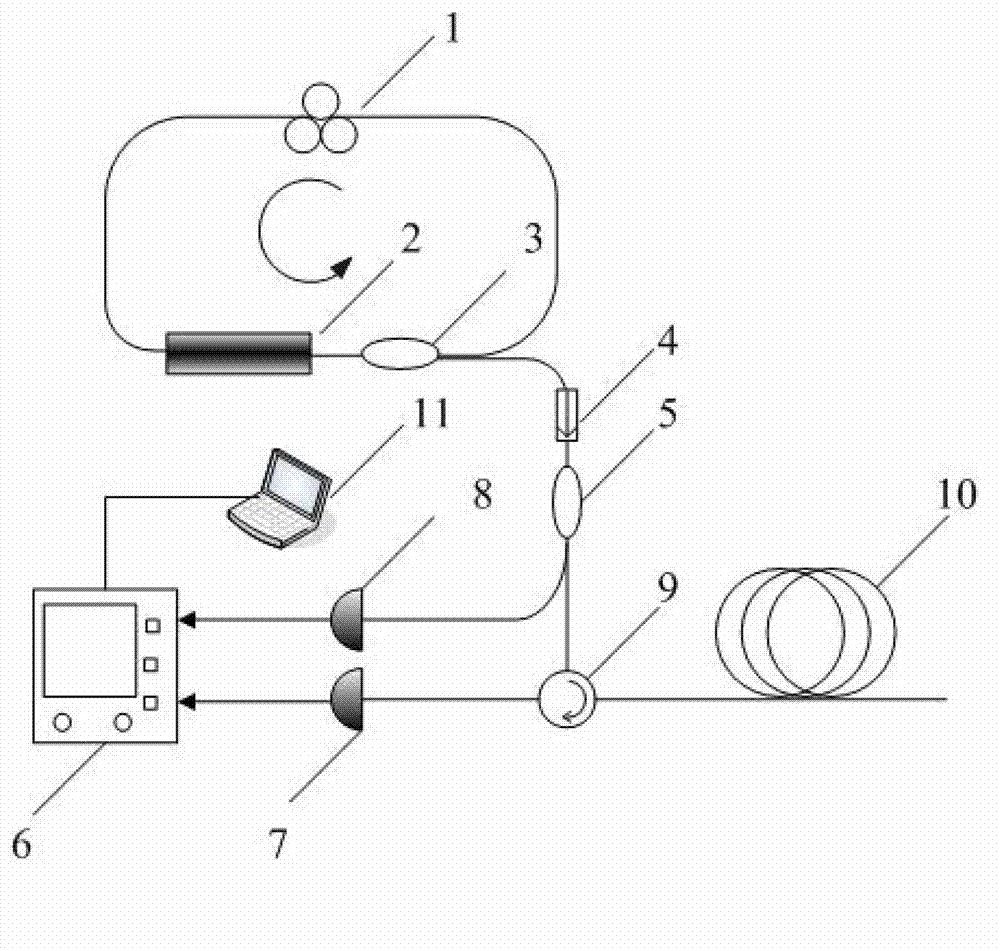
The invention relates to an optical fiber fault detecting system based on an optical fiber laser chaotic signal. The system comprises a chaotic light generator, a first optical fiber coupler, a circulator, a first photoelectric detector, a second photoelectric detector, a signal acquirer and a signal processing device, and is characterized in that the chaotic light generator is an annular cavity consisting of a semiconductor light amplifier, a polarization controller and a second optical fiber coupler; and light in the annular cavity is output from the second optical fiber coupler and enters the first optical fiber coupler after passing through a light isolator. Remote optical fiber breakpoint positioning with high precision is realized, the problems of limitation of transmission light time domain reflectometer distance to precision and low LD external injection type chaotic light time domain reflectometer precision are overcomed, and the detection precision of a chaotic light time domain reflectometer is improved to the mu m level.
Description
technical field [0001] The invention relates to the field of optical time-domain meters, in particular to an optical time-domain meter based on a fiber laser chaotic signal. Background technique [0002] Optical time domain reflectometer OTDR (Optical Time Domain Reflectometer) or backscattering as a characteristic of optical fiber was first confirmed by Barnoskim and Jensen in 1976. OTDR uses Rayleigh scattering and Fresnel reflection to characterize fiber optics. Rayleigh scattering is due to the scattering of optical signals along the optical fiber. The OTDR measures a portion of the scattered light that returns to the instrument port. These backscatter signals indicate the degree of attenuation caused by the fiber. The optical fiber loss is characterized by judging the intensity of backscattered signals detected at different time points, and further through the conversion of time domain and space domain, the trajectory formed on the distance-light intensity icon is a ...
Claims
Login to View More Application Information
Patent Timeline
 IPC IPC(8): H04B10/071
Inventor夏历解振海王元武城池杨成梁
OwnerHUAZHONG UNIV OF SCI & TECH