Sounding device and manufacturing method thereof

A technology for a sound-emitting device and a manufacturing method, applied in the electro-acoustic field, can solve the problems of difficulty in ensuring the consistency of the thickness of the diaphragm and other properties, difficulty in ensuring the consistency of the thickness of the diaphragms of each layer, and inability to meet the working needs of the sound-emitting device. Good performance, simplified process, high product stability

Active Publication Date: 2013-04-17
GOERTEK INC
View PDF8 Cites 29 Cited by
  • Summary
  • Abstract
  • Description
  • Claims
  • Application Information

AI Technical Summary

Problems solved by technology

[0002] In the prior art, the diaphragm of the sounding device is usually made of plastic materials, such as PEI, PEN, PAR, etc., but the single-layer diaphragm made of the above materials has low strength and cannot meet the working needs of the sounding device. Therefore, the diaphragm is usually made of A composite structure formed by multiple single-layer diaphragms of the same material or different materials
Due to the large number of layers of the multi-layer structure of the diaphragm, it is difficult to ensure the consistency of the thickness of each layer of the diaphragm in mass production, and it is difficult to ensure the consistency of the thickness of the diaphragm and other properties, thereby affecting the stability of the product.
[0003] At the same time, the diaphragm forming process of this multi-layer structure needs to combine various diaphragm layers, and the manufacturing process is complicated.

Method used


Image

  • Sounding device and manufacturing method thereof
  • Sounding device and manufacturing method thereof
  • Sounding device and manufacturing method thereof

Examples


Embodiment 1

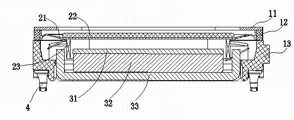
[0025] Embodiment one: if figure 1 As shown, the sound generating device of the present invention includes a vibration system, a magnetic circuit system, and a peripheral frame for accommodating the fixed vibration system and the magnetic circuit system. Wherein the vibration system includes a diaphragm assembly and a voice coil 23 combined with the lower side of the diaphragm assembly; the diaphragm assembly includes a diaphragm 21 and a plastic support 12 combined with the edge of the diaphragm 21; in order to improve the high-frequency characteristics of the diaphragm 21, A rigid composite layer 22 is bonded to the upper surface at the center of the diaphragm 21 . The magnetic circuit system includes a washer 31, a magnet 32 ​​and a basin frame 33 combined from top to bottom. The magnetic circuit system forms a magnetic gap for accommodating the voice coil 23. After the voice coil 23 is connected to an electric signal, it receives an ampere force in the magnetic circuit sys...

Embodiment 2

[0034] Embodiment two: Figure 4It is a cross-sectional view of the diaphragm assembly of the sound-generating device in Embodiment 2 of the present invention. As shown in the figure, compared with Embodiment 1, the present invention also has a second combination with the support 12 injection-molded on the lower side of the support 12. part 211b, the second joint part 211b further increases the joint area between the edge of the diaphragm 21 and the support member 12, thereby increasing the firmness of the bond between the silicone rubber diaphragm 21 and the support member 12. In addition, the second bonding portion 211b is not limited to the structure that is injection-molded and bonded to the lower side of the support member 12, and can also be injection-molded and bonded to the upper side thereof, which can increase the bonding area between the diaphragm 21 and the support member 12 and improve the firmness of the bond. degree.

[0035] The steps of the manufacturing meth...

Embodiment 3

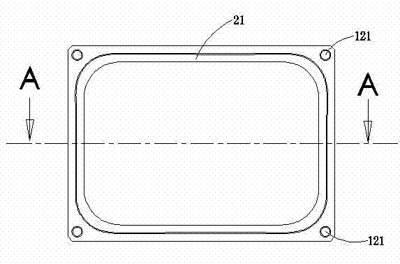
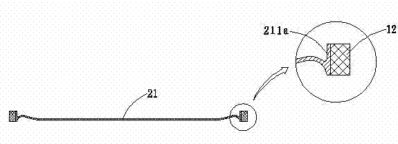
[0037] Embodiment three: as Figure 5 with Image 6 As shown, in this embodiment, the edge of the silicone rubber diaphragm 21 is provided with a first bonding portion 211a that is injection-molded with the inner side wall of the support 12, and a second bond that is injection-molded with both the lower side and the upper side of the support 12. part 211a and the second joint part 211c, this structure further increases the area where the silicone rubber diaphragm 21 and the support member 12 are injection-molded, and improves the firmness of the bond between the diaphragm 21 and the support member 12 . It should be noted that the positioning hole 121 cannot be covered during the injection molding process of the second combining portion 211 a and the second combining portion 211 c with the support member 12 , so as to facilitate the positioning of the diaphragm assembly in subsequent processes.

[0038] The manufacturing process of the sound-generating device in this embodimen...


PUM


Abstract

The invention discloses a sounding device. The sounding device comprises a vibrating diaphragm component, wherein the vibrating diaphragm component comprises a vibrating diaphragm and a plastic supporting element combined at the edge of the vibrating diaphragm; the vibrating diaphragm is of a silicon rubber structure, and is in fixed combination with a supporting element in an injection molding manner; and a combining portion which is in injection molding combination with the supporting element is arranged at the edge of the vibrating diaphragm. The manufacturing method of the sounding device comprises the following steps of: 1, forming an annular plastic supporting element in the injection molding manner through filling plastic material in a shaping mold of the supporting element; and 2, fixing the supporting element, and forming a silicon rubber vibrating diaphragm by filling the silicon rubber material in the shaping mold of the vibrating diaphragm, wherein the shaping mold of the vibrating diaphragm extends to the inner side wall of the supporting element, or on the position of the upper side and/or the lower side wall. The vibrating diaphragm with the structure has excellent consistency, and high product stability; the shaping technology of the vibrating diaphragm is simplified, and the manufacturing process of the product is simplified.

Description

technical field [0001] The invention relates to the field of electroacoustics, in particular to a sounding device and a manufacturing method thereof. Background technique [0002] In the prior art, the diaphragm of the sounding device is usually made of plastic materials, such as PEI, PEN, PAR, etc., but the single-layer diaphragm made of the above materials has low strength and cannot meet the working needs of the sounding device. Therefore, the diaphragm is usually made of A structure composed of multiple single-layer diaphragms of the same material or different materials. Due to the large number of layers of the multi-layer structure of the diaphragm, it is difficult to ensure the consistency of the thickness of each layer of the diaphragm in mass production, and it is difficult to ensure the consistency of the thickness of the diaphragm and other properties, thereby affecting the stability of the product. [0003] At the same time, in the forming process of the diaphrag...

Claims


Application Information

Patent Timeline
Patent Type & Authority Applications(China)
IPC IPC(8): H04R31/00H04R7/02H04R7/16
Inventor 杨健斌江超
Owner GOERTEK INC
Why Eureka
Try Eureka