
Double-station circumferential stitch welding device for heat exchanger

A heat exchanger, double station technology, applied in welding equipment, welding equipment, auxiliary welding equipment and other directions, can solve the problems of multiple rework, difficult welding process, product quality discount, etc., to reduce the number of rework and save manpower and material resources , the effect of reducing production costs

Active Publication Date: 2013-04-24
东莞埃欧热能技术有限公司
View PDF5 Cites 23 Cited by
  • Summary
  • Abstract
  • Description
  • Claims
  • Application Information

AI Technical Summary

Problems solved by technology

[0006] The above-mentioned traditional welding method is inaccurate in positioning. During the welding process, it is easy to make the round holes between the plates deviate or the outer circle between the plate groups deviate. The welding process is very difficult, and the welding effect is extremely poor, resulting in welding The quality of the products that come out is greatly reduced
In addition, the above-mentioned traditional welding methods basically use manual operation. Since the welding process of the heat exchange core requires higher precision, manual operation will cause great human error, and the welding effect is extremely poor, resulting in the need for multiple rework. A lot of manpower and material resources are wasted, which increases the production cost
[0007] In addition, the traditional welding method adopts a single welding method for the round holes between the welding plates, which can only weld the round holes between the plates in turn, and cannot weld two round holes at the same time, which greatly reduces the Welding work efficiency

Method used


Image

  • Double-station circumferential stitch welding device for heat exchanger
  • Double-station circumferential stitch welding device for heat exchanger
  • Double-station circumferential stitch welding device for heat exchanger

Examples


Embodiment Construction

[0031] The present invention will be further described below in conjunction with specific embodiments and accompanying drawings.

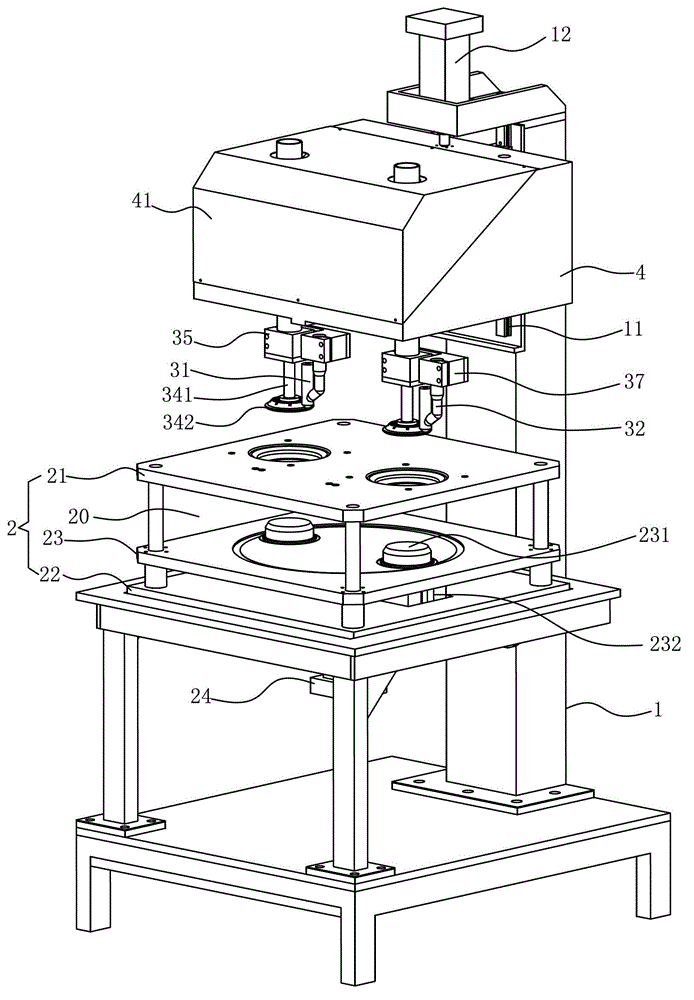
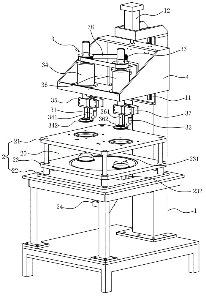
[0032] see Figure 1-7 As shown, the double-station circumferential seam welding equipment for heat exchangers includes: a frame 1, a jig 2 arranged on the frame 1 and used for positioning the plates of the heat exchanger, and a welding device for welding 3.

[0033] The frame 1 is equipped with a mounting table 4 that can move up and down in the frame 1 , and the welding device 3 is installed in the mounting table 4 . Specifically, the frame 1 is equipped with a slide rail 11 for assembling the installation table 4 and a first air cylinder 12 for driving the installation table 4 to move up and down in the slide rail 11 .

[0034] An outer cover 41 is installed on the installation platform 4 , and the outer cover 41 can effectively protect the welding device 3 installed in the installation platform 4 .

[0035] The jig 2 includes: upper and lowe...


PUM


Abstract

The invention discloses a double-station circumferential stitch welding device for a heat exchanger. The stitch welding device comprises a rack, a jig and a welding device for welding, wherein the jig is arranged on the rack and used for positioning sheets of the heat exchanger; the welding device comprises a first welding gun and a second welding gun which are capable of welding inner circles of the sheets of the heat exchanger synchronously and a drive motor for driving the first welding gun and the second welding gun to weld according to circular tracks; the jig comprises upper and lower clamping dies fixedly installed on the rack and a movable clamping plate movably installed between the upper and lower clamping dies, the bearing position for accommodating the sheets of the heat exchanger is formed between the upper clamping die and the movable clamping plate, and two scalable top blocks for limiting the sheets of the heat exchanger are arranged in the movable clamping plate. The stitch welding device which is an automatic welding device is accurate in positioning, capable of welding two inner circles of the sheets of the heat exchanger simultaneously, obvious in welding quality and effects, high in working efficiency and low in production cost.

Description

Technical field: [0001] The invention relates to the technical field of heat exchangers, in particular to a double-station circular seam for heat exchangers with accurate positioning, capable of welding two inner circles of heat exchanger plates at the same time, with remarkable welding quality and high working efficiency Stitch welding equipment. Background technique: [0002] A heat exchanger (English translation: heat exchanger) is a device that transfers part of the heat of a hot fluid to a cold fluid, also known as a heat exchanger. Heat exchangers are common equipment in chemical industry, petroleum, power, food and many other industrial sectors, and play an important role in production. In chemical production, heat exchangers can be used as heaters, coolers, condensers, evaporators and reboilers, etc., and are more widely used. [0003] The existing heat exchangers are dominated by plate and shell heat exchangers, which generally include a shell and a heat exchange ...

Claims


Application Information

Patent Timeline
Patent Type & Authority Applications(China)
IPC IPC(8): B23K10/02B23K37/02B23K37/04
Inventor 黄华东
Owner 东莞埃欧热能技术有限公司
Learn More