High-efficiency self-priming centrifugal submersible aerator

A technology for aerators and submersible motors, applied in water aeration, water/sludge/sewage treatment, sustainable biological treatment, etc., can solve the problem of reducing bubble residence time, accelerating bubble rising speed, and intake negative pressure head Loss and other issues, to reduce the probability of air bubbles merging and becoming larger, improve aeration efficiency, and prolong the residence time

Active Publication Date: 2013-04-24
CHONGQING CHENMING WATER TREATMENT EQUIP
View PDF6 Cites 16 Cited by
  • Summary
  • Abstract
  • Description
  • Claims
  • Application Information

AI Technical Summary

Problems solved by technology

[0005] The disadvantages of these two structures are: when the high-speed air passes through the pipe elbow or the air chamber, additional resistance will be generated, which will cause the loss of the negative pressure head of the intake air, reduce the intake air volume, and reduce the aeration efficiency of the aerator.
A large number of small bubbles in the ring-shaped bubble belt will quickly merge and become larger due to the inability to diffuse in time, causing a sharp decrease in the surface area of ​​the bubbles, resulting in a decrease in the efficiency of dissolved oxygen in water
At the same time, as the diameter of a single bubble increases, its buoyancy in the water increases, which speeds up the rising speed of the bubbles, reduces the residence time of the bubbles in the water, and also reduces the efficiency of dissolved oxygen in water.

Method used


Image

  • High-efficiency self-priming centrifugal submersible aerator
  • High-efficiency self-priming centrifugal submersible aerator
  • High-efficiency self-priming centrifugal submersible aerator

Examples


Embodiment Construction

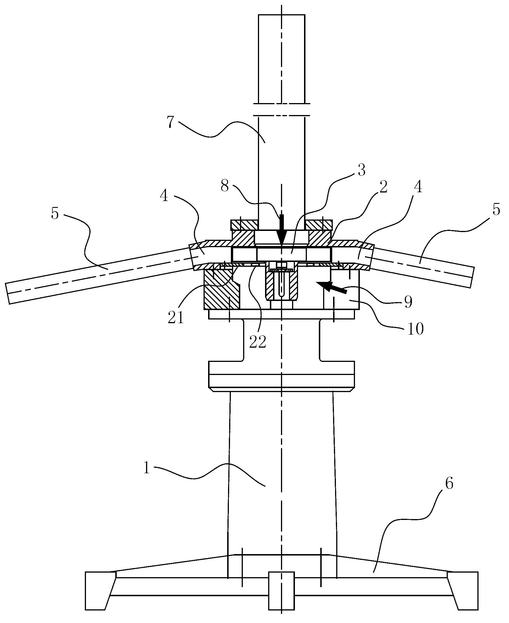
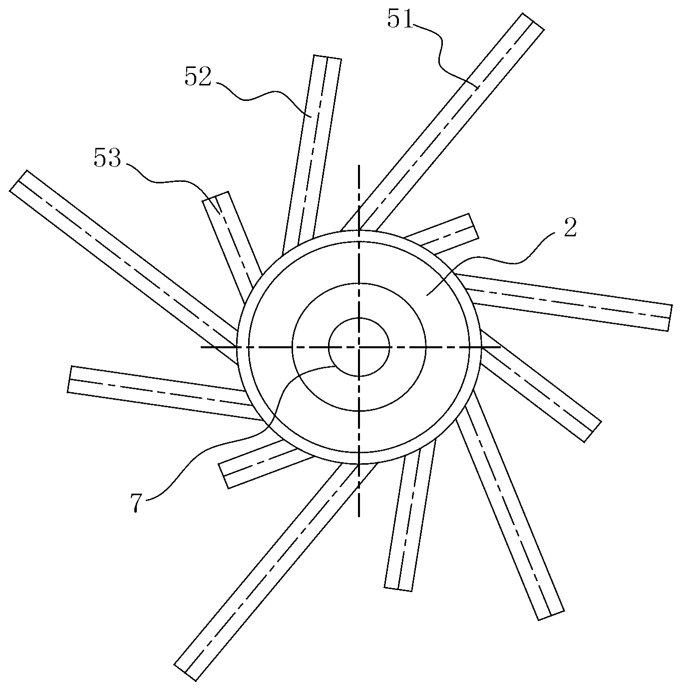
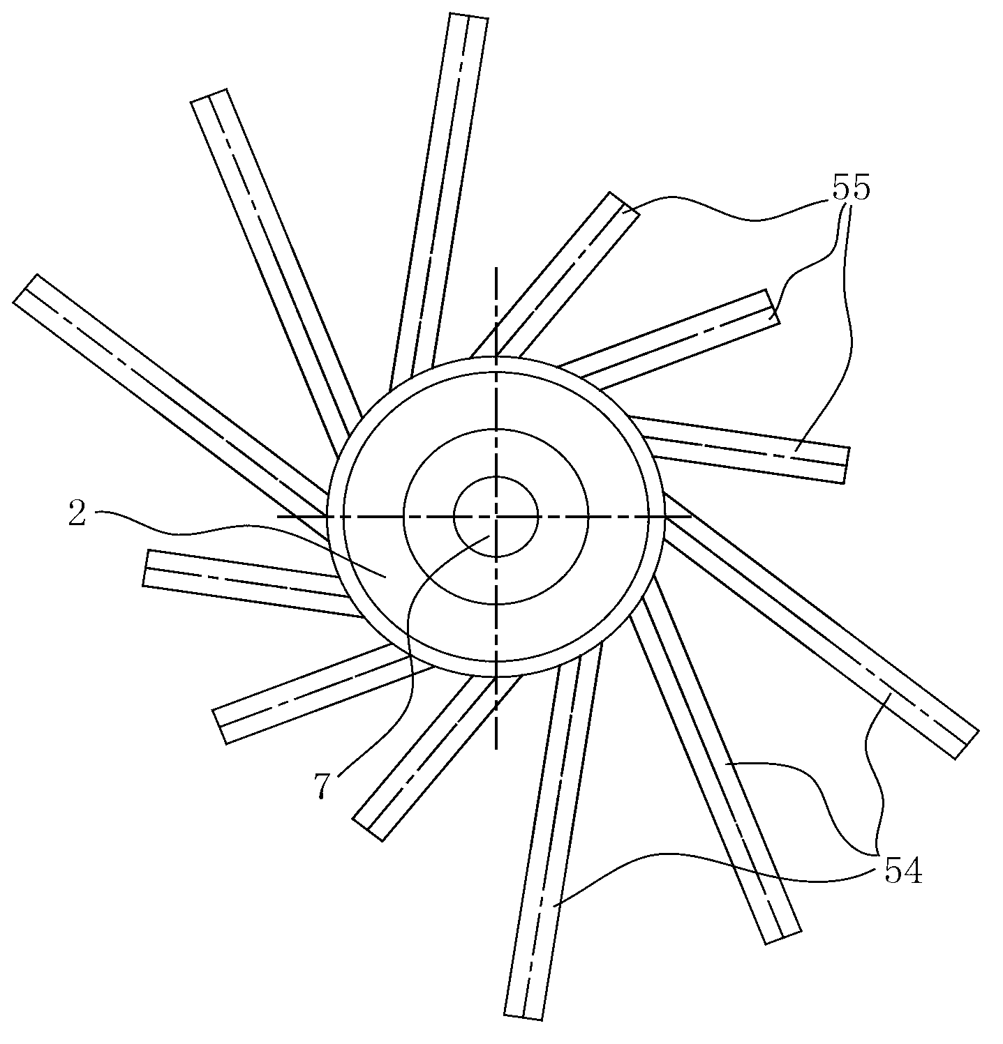
[0020] Such as Figures 1 to 4 The submersible aerator includes a submersible motor 1, the transmission shaft of the submersible motor 1 is connected to the impeller 3 located in the inner cavity of the aeration disc 2, the upper end of the aeration disc 2 is provided with an air inlet, and the lower end is provided with a water inlet, and the aeration disc 2 The flow channels 4 for discharging the water and air mixture into the water are arranged around the periphery, which are all related to the improvement of the present invention. As for how the drive shaft is driven and fixed, the specific structure and arrangement of the aeration disc 2 and the impeller 3 The manner is that those skilled in the art can realize further improvement according to the existing technology or their own creativity, and there are many implementation manners. An improvement of the present invention is that: the flow channel 4 around the aeration pan 2 is arranged obliquely downward. This runner 4...


PUM


Abstract

The invention relates to sewage treatment equipment, particularly a self-priming centrifugal submersible aerator. The invention aims to provide a high-working-reliability high-efficiency self-priming centrifugal submersible aerator. According to the submersible aerator, a drive shaft of a submersible motor is connected with impellers positioned in the inner cavity of an aeration tray; the upper end of the aeration tray is provided with an air inlet, and the lower end is provided with a water inlet; and the periphery of the aeration tray is provided with a flow channel for discharging a water-air mixture into water. The invention is characterized in that the flow channel on the periphery of the aeration tray is arranged obliquely downwards. Preferably, the outlet of the flow channel is connected with a plurality of injection pipes, and the injection pipes are regularly arranged on the periphery of the aeration tray according to lengths. The submersible motor is arranged below the aeration tray. By adopting the technical scheme of the invention, the flow channel in the aeration tray is obliquely downwards instead of horizontal, so that the injected water-air mixed fluid can stir the sludge on the tank bottom, thereby preventing the sludge from settling.

Description

technical field [0001] The invention relates to sewage treatment equipment, in particular to a self-priming centrifugal submersible aerator. Background technique [0002] The self-priming centrifugal submersible aerator is a special equipment for aerating and oxygenating water bodies in the water treatment process. Its working principle is: the transmission shaft of the submersible motor directly drives the semi-open impeller built in the aeration disc to rotate at high speed, and high pressure is generated under the action of the centrifugal force of the rotating impeller, and the air and water are respectively fed from the upper and lower ends of the aeration disc. The mouth is sucked; the impeller communicates with the air inlet pipe leading to the water, and introduces air. There are multiple flow channels around the aeration plate. The water and air mixture enters the flow channel and is fully mixed, then sprays out at high speed in the radial direction from the outlet...

Claims


Application Information

Patent Timeline
Patent Type & Authority Applications(China)
IPC IPC(8): C02F7/00
CPCY02W10/10
Inventor 何祖汉
Owner CHONGQING CHENMING WATER TREATMENT EQUIP
Why Eureka
Try Eureka