Focusing and leveling device

The technology of focusing and leveling device and grating is applied in the direction of exposure device, optics and instrument in photoengraving process, which can solve the problems of difficult installation and adjustment and complicated structure, and achieve the effect of simplifying the difficulty of design and debugging.

Active Publication Date: 2015-05-20
RAINBOW SOURCE LASER RSLASER
View PDF10 Cites 0 Cited by
  • Summary
  • Abstract
  • Description
  • Claims
  • Application Information

AI Technical Summary

Problems solved by technology

Although these methods can achieve clear imaging of each measurement point, they have disadvantages such as complex structure and difficult installation and adjustment.

Method used


Image

  • Focusing and leveling device
  • Focusing and leveling device

Examples


Embodiment Construction

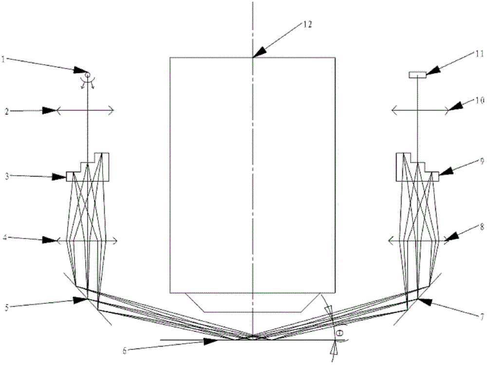
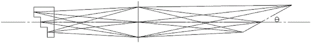
[0011] see figure 1 and figure 2 shown. The focusing and leveling device of the present invention is used on the projection lithography machine 12. The focusing and leveling device includes: an illumination system, an imaging system and a detection system. The feature of the present invention is to use a stepped grating with a height difference as the focusing marks and reference marks.

[0012] The lighting system of the focusing and leveling device is composed of a wide-spectrum light source 1 and a lighting lens 2. The wide-spectrum light source 1 can be composed of a halogen lamp or multiple LEDs. The lighting lens 2 is a Kohler lighting system. In order to obtain a uniform lighting effect, it has a high After being illuminated by the light source, the poor stepped illumination grating 3 is imaged on the silicon wafer 6 through the projection objective lens 4 of the illumination system, reflected by the silicon wafer 6, and then imaged on the reference grating 9 in the ...


PUM


Abstract

A focusing and leveling device for a projection lithography machine comprises a lighting system, an imaging system and a detection system. The device is characterized in that a lighting grating in the lighting system and a reference grating in the imaging system are both stepped grating with height difference. The invention adopts a stepped-type focusing mark; the grating is installed on a stepped prism or a stepped mirror bracket; and at the same time, the reference grating also employs a stepped mark. Thus, design and debugging difficulty of an optical system can be simplified.

Description

technical field [0001] The invention relates to a focusing and leveling device for a projection photolithography machine, in particular to a focusing and leveling device with a grating and a reference grating. Background technique [0002] The focus and leveling device of the projection lithography machine has a large incident angle of light, and it is difficult to ensure that each measurement point is clearly imaged on the silicon wafer, which in turn affects the measurement accuracy. For this reason, in CANON company US 5414515 patent, the method of compensation optics is used to realize clear imaging of each measurement point; in NIKON company US5602399 patent, the method of using inclined prism; in CN 101477319A of SMEE company, the design of inclined mask plate is adopted; in CN 100559278C, reflective stepped prism is used The method; Beijing Institute of Technology CN 100592214C adopts the method of microlens array to realize. Although these methods can achieve clear ...

Claims


Application Information

Patent Timeline
Patent Type & Authority Patents(China)
IPC IPC(8): G03F9/00G03F7/20
Inventor 刘广义韩晓泉王宇周翊
Owner RAINBOW SOURCE LASER RSLASER
Why Eureka
Try Eureka