Hundred-megawatt level heavy type flywheel energy storage system based on gas magnetic fluid float cylinder suspension

A flywheel energy storage, megawatt-level technology, applied in the field of energy storage systems, can solve the problems of large magnetic suspension current of heavy shafts, difficult suspension of shafts, and unfavorable popularization. infinite effects

Inactive Publication Date: 2013-04-24
成志东
View PDF3 Cites 7 Cited by
  • Summary
  • Abstract
  • Description
  • Claims
  • Application Information

AI Technical Summary

Problems solved by technology

[0034] The superconducting magnetic levitation energy storage uses superconducting magnetic levitation technology to levitate the rotating shaft supporting the flywheel, but only relying on magnetic levitation to achieve the rotating shaft levitation, then the current required for the heavy-duty rotating shaft magnetic levitation will be very large, and the design of the rotating shaft levitation will be very difficult. Not conducive to popularization

Method used


Image

  • Hundred-megawatt level heavy type flywheel energy storage system based on gas magnetic fluid float cylinder suspension
  • Hundred-megawatt level heavy type flywheel energy storage system based on gas magnetic fluid float cylinder suspension
  • Hundred-megawatt level heavy type flywheel energy storage system based on gas magnetic fluid float cylinder suspension

Examples


no. 1 example

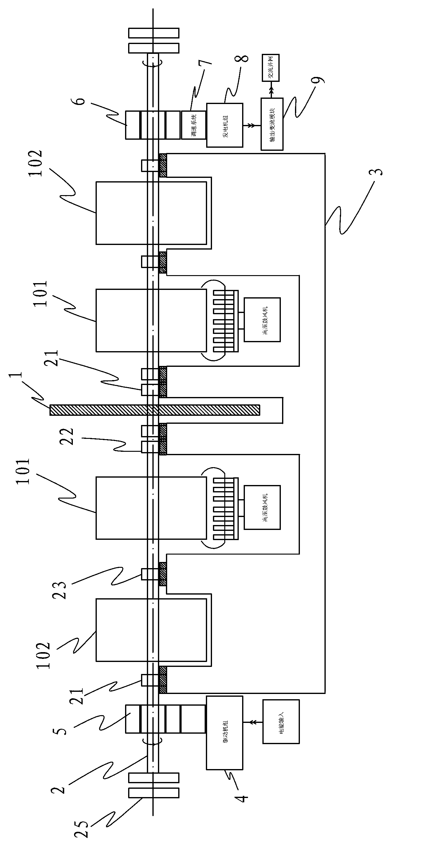
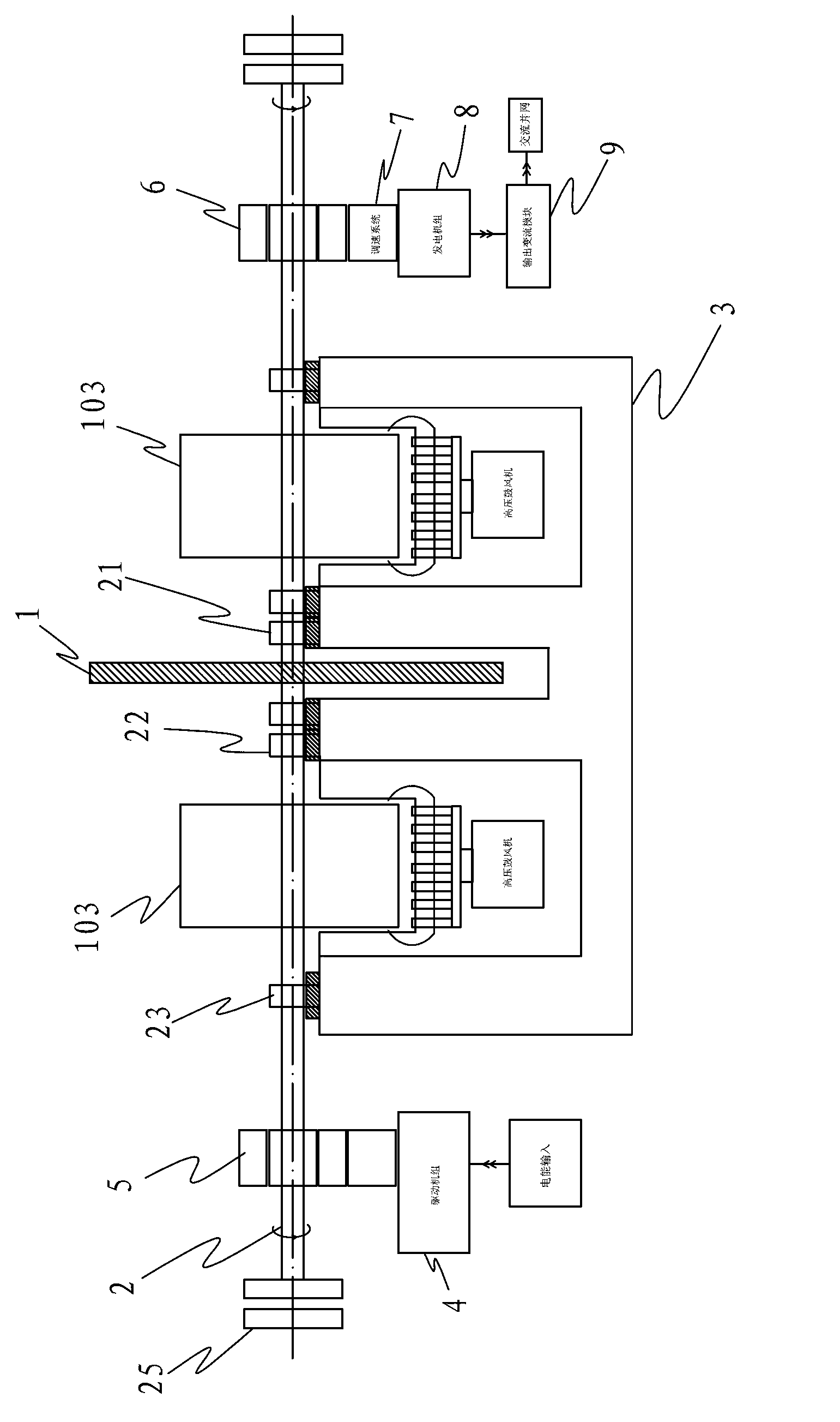
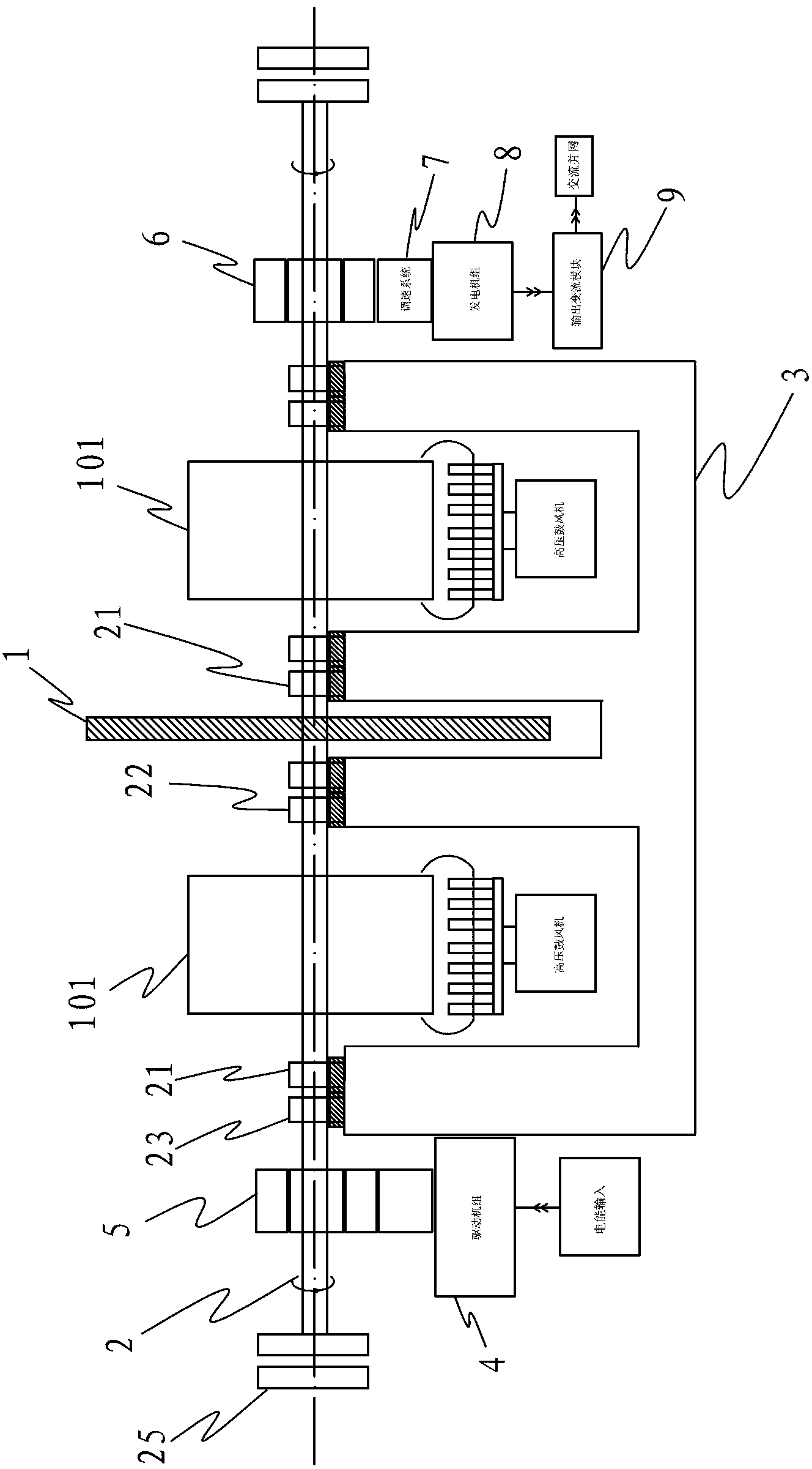
[0117] refer to figure 1, the first embodiment of the present invention includes a base 3, a rotating shaft 2 is arranged on the base 3, a heavy-duty flywheel 1 is arranged in the middle of the rotating shaft 2, and a plurality of discrete air-cushion buoys 101 and magnetic levitation are arranged on the rotating shaft 2 of this embodiment The buoys 102, the air cushion buoys 101 and the magnetic levitation buoys 102 are respectively symmetrically distributed around the heavy flywheel 1. A high-pressure blower is arranged below the air-cushion buoy 101, which suspends the air-cushion buoy 101 by blowing high-pressure gas to provide upward buoyancy for the rotating shaft 2; The electromagnet array or the permanent magnet array, the electromagnet array is arranged in the buoy seat, after the electromagnet array is energized, it generates magnetic force to make the magnetic levitation buoy 102 float, and provides upward buoyancy for the rotating shaft 2 . During normal use, pref...


PUM


Abstract

The invention discloses a hundred-megawatt level heavy type flywheel energy storage system based on gas magnetic fluid float cylinder suspension. The hundred-megawatt level heavy type flywheel energy storage system based on the gas magnetic fluid float cylinder suspension comprises a heavy type flywheel, a rotating shaft, a driving unit and an output unit. A float cylinder is arranged on the rotating shaft, and the float cylinder is one separation or combination of an air cushion float cylinder, a magnetic suspension float cylinder and a fluid float cylinder. The float cylinder is added on the rotating shaft, load bearing capability of the rotating shaft is improved, and the problem that a heavy type flywheel can not be adopted by an existing flywheel energy storage system is solved. The hundred-megawatt level heavy type flywheel energy storage system has the advantages of being high in energy storage efficiency, strong in dilatation capability and wide in energy storage scale, and has the advantages of being high in power density, long in service life, limitless in charge-discharge times, free-of-pollution and the like as traditional flywheel energy storage technology. The hundred-megawatt level heavy type flywheel energy storage system simultaneously is low in construction requirement, is mainly used in flat suppression fluctuation and smooth grid-tied, can be used for constructing of a super-large scale energy storage pitch peak power station, and can also be used as a distribution type intelligent microgrid energy storage core.

Description

technical field [0001] The invention relates to an energy storage system, in particular to a heavy-duty flywheel energy storage system. Background technique [0002] Large-scale consumption and smooth grid integration of wind power, solar energy and other highly volatile new energy sources have always been thorny issues, seriously restricting the healthy development of wind power, solar energy and other new energy sources. [0003] In order to consume highly volatile new energy on a large scale in a timely manner, there are two key points: one is to build an "economical and large-scale energy storage system" to smoothly connect to the grid; at the same time, as a transfer station for energy, temporarily Second, it is necessary to vigorously increase the transmission capacity of UHV long-distance transmission and transmit electric energy away in a timely manner. [0004] One way to increase transmission capacity is to use flexible DC transmission technology, which can solve ...

Claims


Application Information

Patent Timeline
Patent Type & Authority Applications(China)
IPC IPC(8): H02K7/02F16C32/06F16C32/04
CPCY02E60/16
Inventor 成志东
Owner 成志东
Why Eureka
Try Eureka