
Full bridge topology power supply, control method and communication equipment

A technology of topology and power supply device, which is applied in communication equipment, control of full-bridge topology power supply, and field of full-bridge topology power supply. And primary side circulation, reliability and efficiency issues, to achieve the effect of reducing the source-drain voltage peak of the secondary rectifier tube, improving application reliability, and small cycle energy

Active Publication Date: 2013-04-24
HUAWEI TECH CO LTD
View PDF6 Cites 18 Cited by
  • Summary
  • Abstract
  • Description
  • Claims
  • Application Information

AI Technical Summary

Problems solved by technology

[0004] The full bridge circuit is used to solve the wide range of medium and high power applications; due to the demand for high power density, in order to reduce the volume of magnetic components, it is usually achieved by increasing the switching frequency; usually the hard-switched full-bridge is turned on because the primary switch is in hard-switching mode. The loss increases with the switching frequency. Due to the rapid turn-off of the secondary side switch of the hard-switched full bridge and the high current conversion caused by the hard switching of the primary side, the reverse recovery of the secondary side rectifier tube brings a large voltage spike and reverse recovery loss. , and this brings reliability and efficiency problems; phase-shifted full-bridge technology is difficult to solve the soft switching and primary side circulation problems in the full load range, and the phase-shifted control method is complicated

Method used


Image

  • Full bridge topology power supply, control method and communication equipment
  • Full bridge topology power supply, control method and communication equipment
  • Full bridge topology power supply, control method and communication equipment

Examples


Embodiment Construction

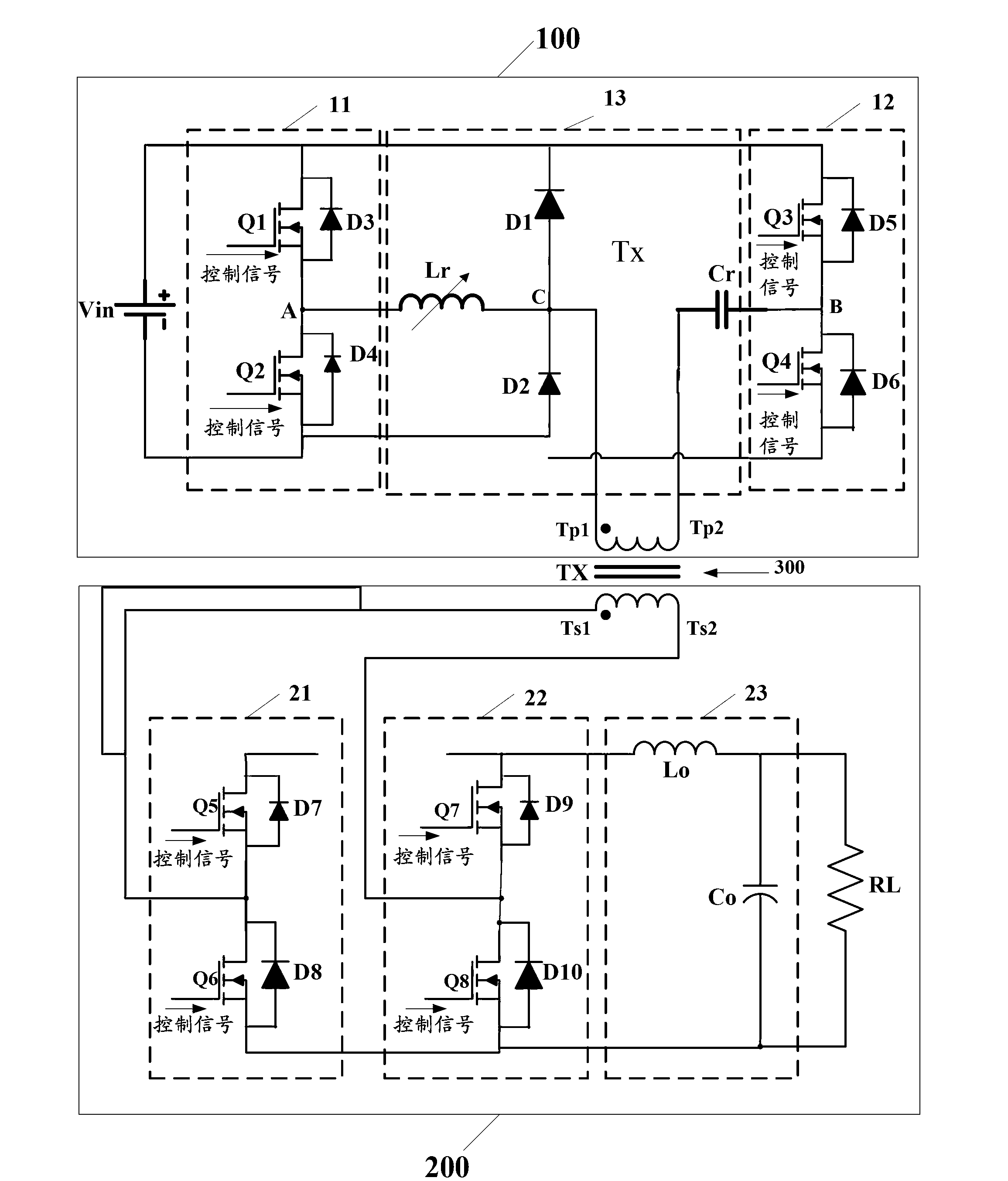
[0039] Embodiments of the present invention provide a full-bridge topology power supply, a control method for the full-bridge topology power supply, and a communication device, in order to improve the soft switching of the full-bridge circuit in the power supply, improve circuit reliability and light-load conversion efficiency.

[0040] In order to enable those skilled in the art to better understand the solutions of the present invention, the following will clearly and completely describe the technical solutions in the embodiments of the present invention in conjunction with the drawings in the embodiments of the present invention. Obviously, the described embodiments are only It is an embodiment of a part of the present invention, but not all embodiments. Based on the embodiments of the present invention, all other embodiments obtained by persons of ordinary skill in the art without making creative efforts shall fall within the protection scope of the present invention.

[0...


PUM


Abstract

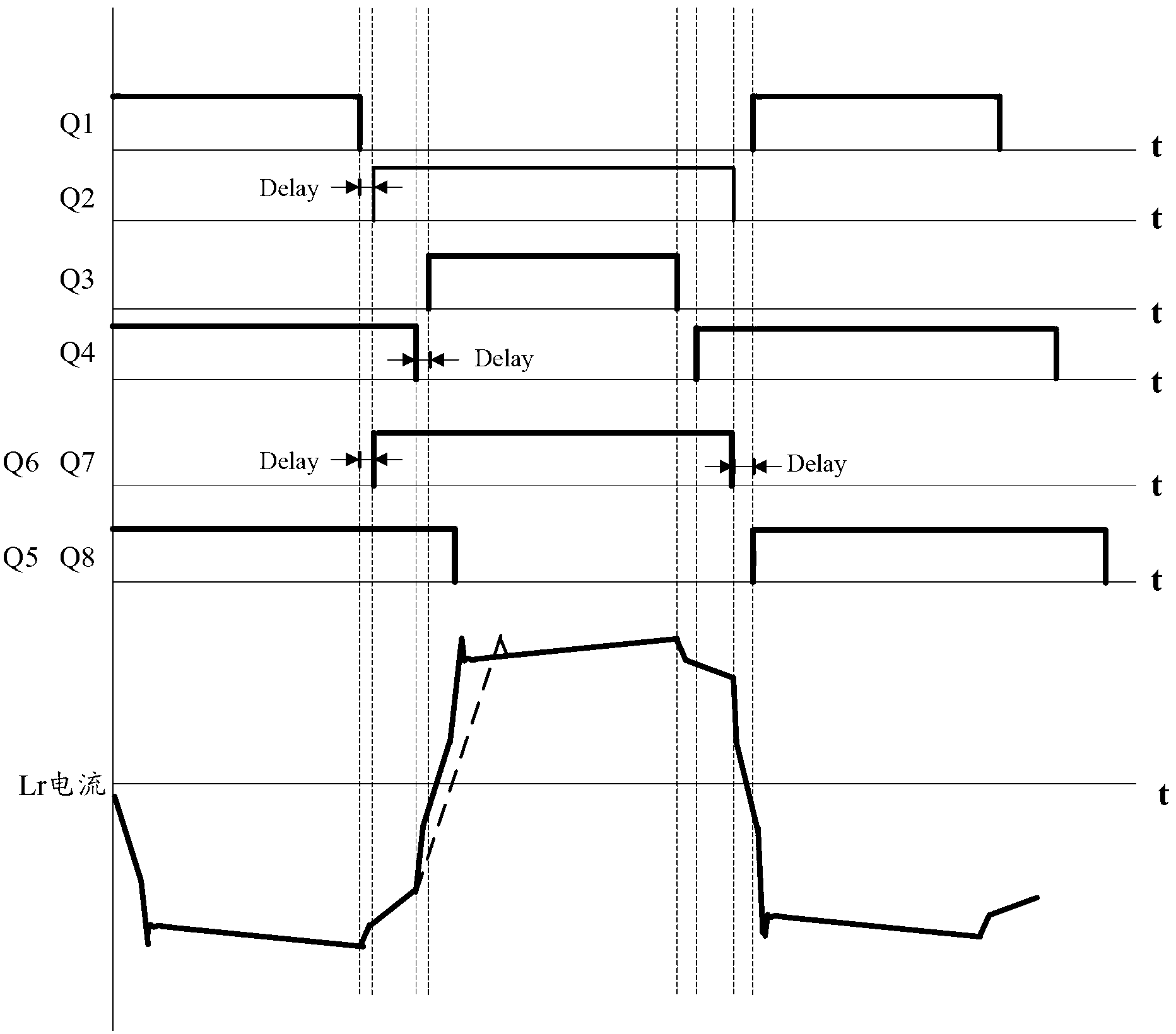
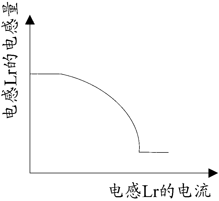
The invention discloses a full bridge topology power supply, a control method and communication equipment. An inductance clamping circuit capable of self-adjusting resonance is arranged in a full bridge topology power supply device, inductance value features can be automatically adjusted with the utilization self-adjusted resonance inductance in the inductance clamping circuit and according to the size of passed current, a control circuit controls each switch tube of a full bridge topology, wide zero voltage switch load range, small circulation energy and small duty ratio loss are achieved, and therefore light loading vice side rectifying loss is reduced, light loading converting efficiency is enhanced, performance of flexible switches of a full bridge is improved, wide load range zero voltage opening up of primary side switch tubes of the full bridge is favorable for being achieved, switch loss is reduced, and efficiency of full load range is improved. Besides, the changing rate of primary side current is lowered by the self-adjusted resonance inductance, the vice side rectifier tube voltage spike is clamped through the self-adjusting resonance inductance clamping circuit, and therefore vice side rectifier tube source drain electrode voltage spike is lowered, and application reliability is improved.

Description

technical field [0001] The invention relates to the technical field of power supplies, in particular to a full-bridge topological power supply, a control method for the full-bridge topological power supply, and a communication device. Background technique [0002] High power density has become one of the development directions of future switching converters. [0003] The power supply can be regarded as a product form of the switching converter. Switching converters include, for example: alternating current to direct current (AC-DC, Alternating Current-Direct Current) switching converters, DC-DC switching converters, and AC-AC switching converters. For example, an AC-DC converter can be used in the power supply to convert the AC input voltage into a DC bus voltage (usually 48V), and then the DC-DC converter can be used to convert the DC bus voltage into a DC voltage of the required size for the load. [0004] The full bridge circuit is used to solve the wide range of medium...

Claims


Application Information

Patent Timeline
Patent Type & Authority Applications(China)
IPC IPC(8): H02M3/335H02M1/08
Inventor 侯召政傅电波
Owner HUAWEI TECH CO LTD
Learn More