Working wheel for road building machine

A technology of road construction machinery and working wheels, which is applied in roads, roads, buildings, etc., can solve the problems of limited compaction range, and achieve the effects of avoiding damage to structures, wide application range, and reasonable design

Inactive Publication Date: 2013-05-01
YTO LUOYANG CONSTR MASCH CO LTD
View PDF5 Cites 2 Cited by
  • Summary
  • Abstract
  • Description
  • Claims
  • Application Information

AI Technical Summary

Problems solved by technology

These types of working wheels operate under certain compaction conditions, and the compaction range is limited

Method used


Image

  • Working wheel for road building machine
  • Working wheel for road building machine
  • Working wheel for road building machine

Examples


Embodiment 1

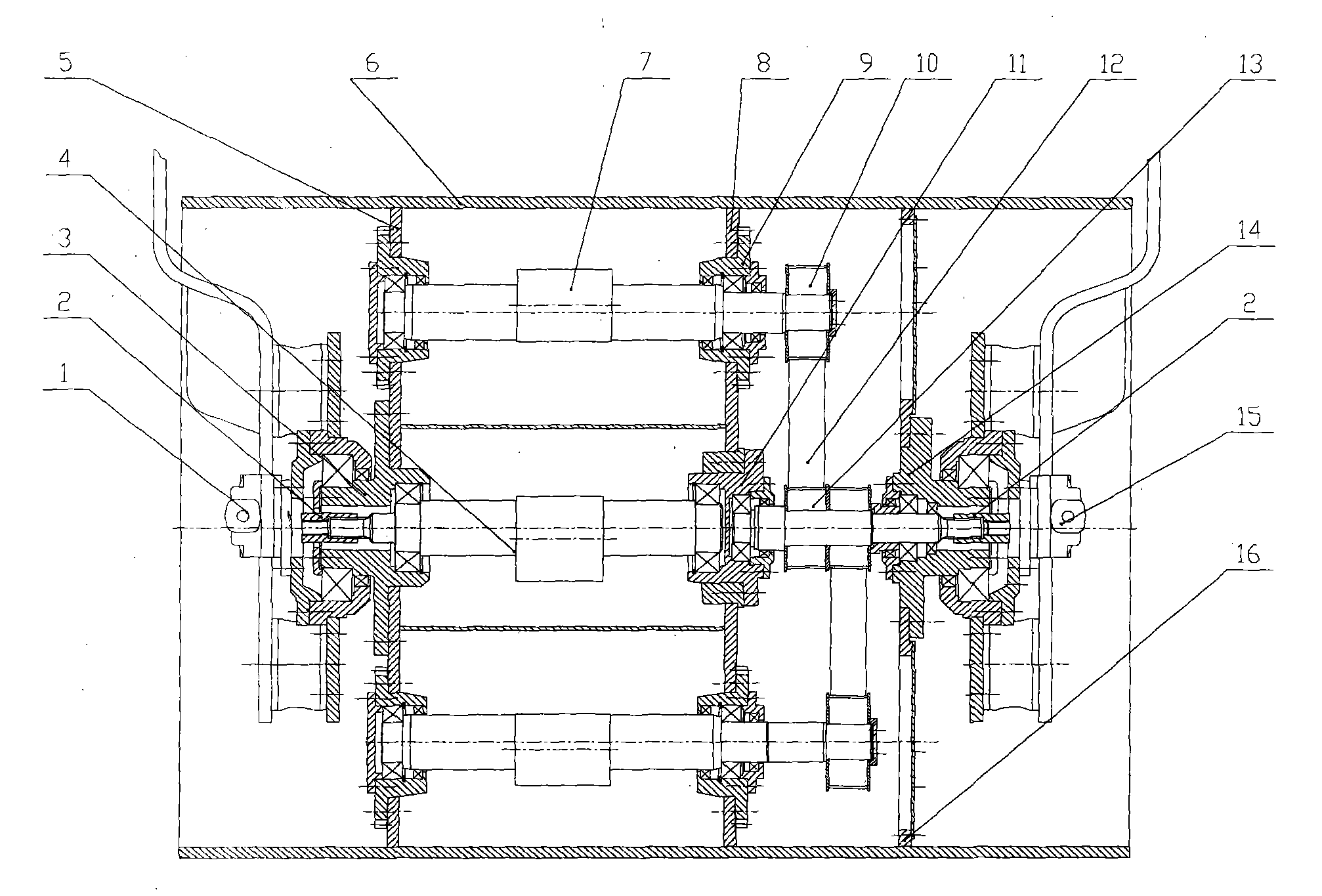
[0021] As shown in the figure; left panel 5, middle panel 8, and right panel 16 are respectively arranged in the working wheel cylinder body 6 of the road construction machinery, and the centers of left panel 5, middle panel 8, and right panel 16 are pre-prepared respectively. Concentric shaft holes are reserved; the left vibration bearing seat 3 is set in the reserved shaft hole in the middle of the left width plate 5, and the bearing is set in the left vibration bearing seat 3, and the middle bearing seat 11 is set in the reserved hole in the middle of the middle width plate 8, and the middle bearing Bearings are set in the reserved shaft holes of the seat 11, the vibration eccentric shaft 4 is set in the bearings of the left width plate 5 and the middle width plate 8, the left vibration motor 1 is set on the left side of the vibration eccentric shaft 4, the left vibration motor 1 and the vibration eccentric shaft The spline connection sleeve 2 is arranged between 4; the bear...

Embodiment 2

[0023] As shown in the figure; two pairs of eccentric shaft holes are symmetrically reserved on both sides of the central shaft hole of the left panel 5 and the middle panel 8, and a bearing seat 9 is arranged in the eccentric shaft hole, and a bearing is arranged in the bearing seat 9, and the left panel 5 and the The oscillating eccentric shaft 7 is set in the bearing of the medium-width plate 8, and the shaft head on the right side of the oscillating eccentric shaft 7 is respectively provided with a driven toothed pulley 10, which corresponds to the pulley of the driving shaft toothed pulley 13 It is provided that a toothed belt 12 is set between the driven toothed pulley 10 and the driving shaft toothed pulley 13 .

Embodiment 3

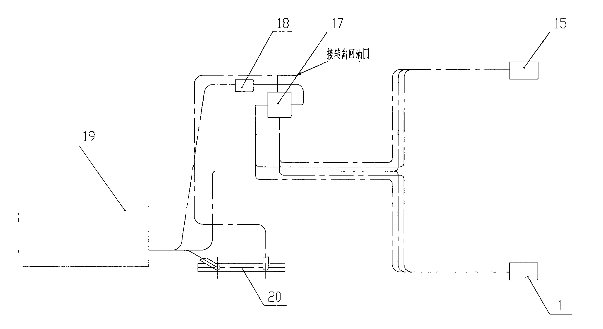
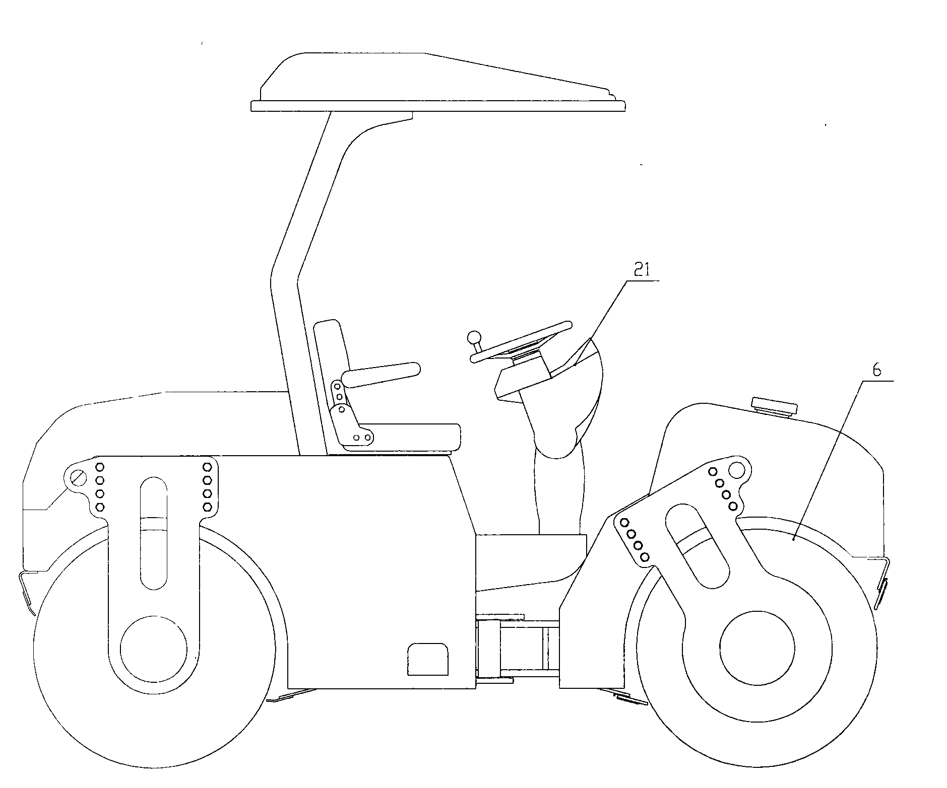
[0025] An electronically controlled instrument panel is installed in the cab of the road construction machinery. An instrument panel 21 is arranged on the electronically controlled instrument panel. A reversing switch is arranged on one side of the instrument panel 21. A control circuit is arranged between the reversing switch and the electromagnetic reversing valve 17. A hydraulic pipeline is arranged between the reversing valve 17 and the hydraulic oil tank 19, a hydraulic pump 18 is arranged between the hydraulic pipelines, and two hydraulic pipelines are arranged on the other side of the electromagnetic reversing valve 17, and one hydraulic pipeline is the electromagnetic reversing valve 17 The hydraulic pipeline with the left vibration motor 1, and the other hydraulic pipeline is the hydraulic pipeline between the electromagnetic reversing valve 17 and the right oscillating motor 15; the oil return pipeline between the hydraulic oil tank 19 and the electromagnetic reversing...


PUM


Abstract

The invention discloses a working wheel for a road building machine. A left plate, a center plate and a right plate are arranged in a working wheel barrel of the road building machine; a vibrating eccentric shaft is arranged at the center between the left plate and the center plate; two oscillating eccentric shafts are arranged on the two sides of the center; under different working condition requirements, the road building machine controls a magnetic exchange valve to switch two hydraulic pipelines of a hydraulic pump through an electric-control manipulation change-over switch; the vibrating eccentric shaft is driven by a motor; the two oscillating eccentric shafts are driven by another motor; and vibration compaction and oscillation compaction are conducted on a working surface by controlling the working wheel barrel. The working wheel has dual purposes and does not generate mutual interference; vibration and oscillation can be independent; the investment of equipment is reduced; and an application range is expanded.

Description

technical field [0001] The invention relates to a road construction machine, in particular to a road construction machine working wheel. Background technique [0002] At present, the commonly used working wheels of domestic road rollers mainly have the following structural forms: one is the pressure wheel of static rolling, which can be used as a driving wheel or a steering wheel, and it is compacted entirely by its own quality, and the operation efficiency is low. One is a vibrating wheel with an eccentric device on the central axis. The high-speed rotation of the eccentric shaft causes the vibrating wheel to generate non-directional vibration, so that the vibrating wheel body produces a centrifugal force in the circumferential direction, which has a deep impact on the subgrade and road surface and has a good compaction effect. The number of rolling times is small and the quality of the whole machine is small, but it also has the disadvantage that it is easy to cause damage...

Claims


Application Information

Patent Timeline
Patent Type & Authority Applications(China)
IPC IPC(8): E01C19/28
Inventor 房升义韩长太张学辉张青蒋宝民胡战伟徐小莲刘卫民徐立
Owner YTO LUOYANG CONSTR MASCH CO LTD
Why Eureka
Try Eureka