Flexible pile cap for composite foundation

A composite foundation and flexible pile technology, applied in sheet pile wall, foundation structure engineering, construction, etc., can solve problems such as uncoordinated deformation, and achieve the effect of increasing bearing capacity, reducing settlement, and convenient installation and layout.

Inactive Publication Date: 2013-05-01
XIAN UNIV OF SCI & TECH
10 Cites 11 Cited by

AI-Extracted Technical Summary

Problems solved by technology

[0005] The technical problem to be solved by the present invention is to provide a flexible pile cap for composite foundation, which is simple in structure, reasonable in design, low in engineering cost, c...

Abstract

The invention discloses a flexible pile cap for a composite foundation. The flexible pile cap comprises a horizontal base, a plurality of inclined stressed rods and circular hoops, wherein the horizontal base is arranged at the top of a reinforcing pile; the inclined stressed rods are arranged above the horizontal base along the peripheral direction; the circular hoops are arranged on the inclined stressed rods; the inclined stressed rods are integrally fastened and connected through the circular hoops; the bottoms of the inclined stressed rods are all fixed on the horizontal base; the inclined stressed rods are gradually outward inclined from bottom to top; the quantity of the inclined stressed rods is not less than 3; the bottoms of the inclined stressed rods are all arranged on a same circle with a diameter d; the horizontal base is arranged right above the top of the reinforcing pile; and the horizontal base, the inclined stressed rods and the circular hoops form a combined pile cap. The flexible pile cap for the composite foundation has the advantages of simple structure, reasonable design, low construction cost, convenience in processing, manufacturing and constructing, good use effect and capability of effectively solving the deformation and discordance problems of a pile part and an inter-pile soil part of the present pile net composite foundation.

Application Domain

Technology Topic

Image

  • Flexible pile cap for composite foundation
  • Flexible pile cap for composite foundation
  • Flexible pile cap for composite foundation

Examples

  • Experimental program(13)

Example Embodiment

[0047] Example 1
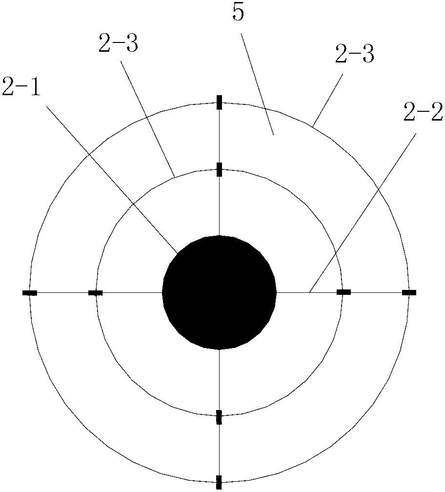
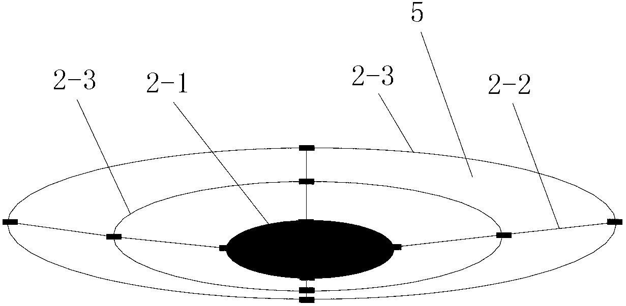
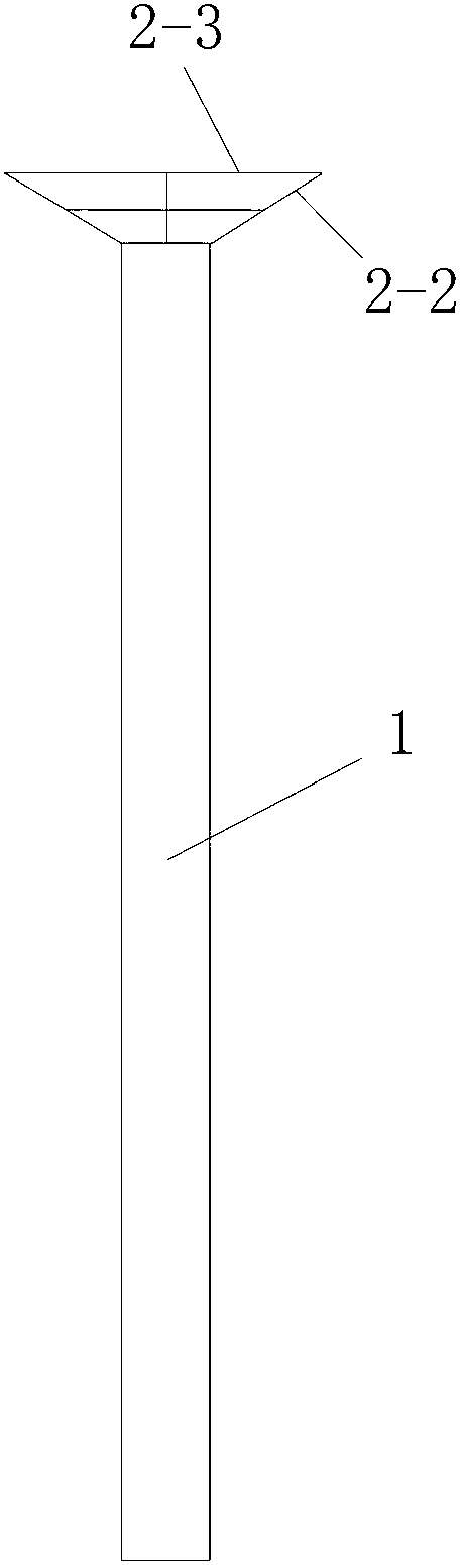
[0048] Such as figure 1 , figure 2 and image 3 As shown, the present invention includes a horizontal base 2-1 arranged on the top of the reinforced pile 1, a plurality of oblique force-bearing rods 2-2 arranged above the horizontal base 2-1 in the circumferential direction, and a plurality of said The circular ferrule 2-3 on the oblique force-bearing rod 2-2, a plurality of the oblique force-bearing rods 2-2 are fastened and connected into one body by the circular ferrule 2-3, and the plurality of The bottoms of the diagonally stressed rods 2-2 are fixed on the horizontal base 2-1, and the multiple diagonally stressed rods 2-2 are gradually inclined outward from bottom to top. The number of the multiple oblique force-bearing rods 2-2 is not less than three. The structure and size of the multiple oblique force-bearing rods 2-2 are all the same, and the bottom ends of the multiple oblique force-bearing rods 2-2 are all arranged on the same circle with the diameter d, the horizontal base 2-1 is arranged directly above the top of the reinforced pile 1. The horizontal base 2-1, a plurality of the oblique force-bearing rods 2-2 and a plurality of the circular hoop 2-3 form a combined pile cap. The circular hoop 2-3 is arranged horizontally, the number of the circular hoop 2-3 is one or more, and each of the circular hoop 2-3 is connected to a plurality of the diagonal The force rod 2-2 is fixedly connected as a whole. In addition, a plurality of the circular hoops 2-3 are arranged on the plurality of oblique force-bearing rods 2-2 from top to bottom.
[0049] In this embodiment, the outer side of the combined pile cap is covered with a layer of geotextile 5, which is not shown in the figure.
[0050] In actual processing, the geotextile 5 may not be covered on the outer side of the combined pile cap. Moreover, when it is necessary to coat a layer of geotextile 5 on the outside of the combined pile cap, after the production of the combined pile cap is completed, the geotextile 5 may be directly covered on the outside of the combined pile cap.
[0051] In this embodiment, a plurality of the oblique force-bearing rods 2-2 are evenly arranged along the circumferential direction.
[0052] In this embodiment, the number of the plurality of diagonally stressed rods 2-2 is 4, and the four diagonally stressed rods 2-2 are evenly arranged in the circumferential direction.
[0053] In actual processing, the number of the oblique force-bearing rods 2-2 can be adjusted accordingly according to actual needs; and the arrangement of the oblique force-bearing rods 2-2 can be made according to specific needs. The position is adjusted accordingly.
[0054] The oblique force-bearing rod 2-2 is a linear steel bar, an arc-shaped steel bar or a broken line-shaped steel bar. In this embodiment, the diagonally stressed rod 2-2 is a linear steel bar.
[0055] In this embodiment, the number of the circular hoop 2-3 is two. In addition, the two circular ferrules 2-3 are respectively a circular ferrule 1 arranged in the middle of the plurality of obliquely force-bearing rods 2-2 and a circular ferrule arranged on the plurality of obliquely-forced rods 2-2. 2 Round hoop at the top two.
[0056] In actual processing, the number of the circular hoop 2-3 and the arrangement position of each circular hoop 2-3 can be adjusted according to specific needs.
[0057] In this embodiment, the cross-section of the reinforced pile 1 is circular, and d≤D1, where D1 is the diameter of the reinforced pile 1, and d is the circumference of the bottom end of the plurality of diagonally stressed rods 2-2. diameter of.
[0058] In this embodiment, the diameter D1 of the reinforced pile 1 (ie pile diameter)=d. Moreover, the value of d can be adjusted accordingly according to actual needs. In actual construction, the cross section of the reinforced pile 1 may also be rectangular or regular polygon.
[0059] In actual processing, the horizontal base 2-1 is a circular base, an annular base or a regular polygon base. The outer diameters of the circular base and the annular base are not greater than d, the diameter of the circumscribed circle of the regular polygon base is not greater than d, where d is the bottom end of the plurality of oblique force-bearing rods 2-2 The diameter of the laid circle.
[0060] In this embodiment, the horizontal base 2-1 is a circular base, and the circular base is a circular steel plate. In actual use, the horizontal base 2-1 may also adopt a circular base or a regular polygon base.
[0061] In this embodiment, the outer diameter of the circular base is d. In actual processing, the outer diameter of the circular base can be adjusted accordingly according to specific needs.
[0062] In actual processing, the oblique force-bearing rod 2-2 is a steel bar or a bamboo strip. The circular ferrule 2-3 is a steel bar, a rigid plastic strip or a bamboo strip; when the circular ferrule 2-3 and the oblique force rod 2-2 are both steel bars, the circular ferrule 2-3 and the oblique force-bearing rod 2-2 are fixedly connected by lashing or welding; when the round hoop 2-3 is a hard plastic strip or a bamboo strip, the round hoop 2-3 and the oblique force rod 2-2 are fixedly connected by lashing.
[0063] In this embodiment, the diagonally stressed rod 2-2 is a steel bar, the circular ferrule 2-3 is a steel bar, and the circular ferrule 2-3 and the diagonally stressed rod 2-2 are They are fixedly connected by welding. In addition, the bottoms of a plurality of obliquely stressed rods 2-2 are welded and fixed on the horizontal base 2-1.
[0064] In actual use, the round hoop 2-3 can also be a hard plastic strip or bamboo strip; and when the round hoop 2-3 is a hard plastic strip or bamboo strip, the round sleeve The hoop 2-3 and the oblique force-bearing rod 2-2 are fixedly connected in a lashing manner. Specifically, a tie wire or a bamboo strip may be used for lashing and fixing.
[0065] In actual use, when bamboo strips are used for the round hoop 2-3, the bamboo has the characteristics of light body but exceptionally hard texture, and therefore can be effectively applied to the present invention. According to experiments, the shrinkage of bamboo is very small, but the elasticity and toughness are high. The tensile strength along the grain is 170Mpa, and the compressive strength along the grain is 80M Pa. Especially, the highest tensile strength along the grain is 280Mpa.
[0066] In this embodiment, combining Figure 4 The number of the reinforced piles 1 is multiple, the number of the combined pile caps is multiple, and the multiple combined pile caps are respectively arranged on the pile tops of the multiple reinforced piles 1. A plurality of the reinforced piles 1 are all arranged in the reinforced soft soil foundation 3, and a cushion layer 4 is laid on the reinforced soft soil foundation 3, and a plurality of the combined pile caps are all arranged on the cushion layer 4 within.
[0067] In actual construction, the cushion layer 4 is a sand-gravel cushion or a crushed stone cushion.
[0068] The top ends of the multiple oblique force-bearing rods 2-2 are all arranged on the same circle with a diameter of D3, and D3=1.5d~5d, and the distance between the top end and the bottom end of the obliquely force-bearing rod 2-2 The angle α between the connecting line and the horizontal plane is 5°~65°.
[0069] In this embodiment, D3=4d, and the included angle α is 30°.
[0070] During specific processing, the size of D3 and the included angle α can be adjusted accordingly according to actual needs. In actual processing, when the distance between two adjacent reinforced piles 1 is larger, the value of D3 is larger, and the value of included angle α is smaller; on the contrary, when the distance between two adjacent reinforced piles 1 The smaller the distance between the piles, the smaller the value of D3, and the larger the value of the angle α. In addition, when the load on the soil between two adjacent reinforced piles 1 is greater, the value of D3 is smaller, and the value of the included angle α is larger; on the contrary, when two adjacent reinforcement piles 1 The smaller the load on the soil between the piles 1, the larger the value of D3 and the smaller the value of the included angle α.
[0071] In this embodiment, the diameter of the diagonally stressed rod 2-2 is Φ8mm~Φ20mm. In actual processing, the diameter of the diagonally stressed rod 2-2 can be adjusted according to the value of D3 and the load on the soil between the two adjacent reinforced piles 1.
[0072] In actual construction, after the multiple reinforcement piles 1 are constructed and formed, a cushion layer 4 is first laid on the reinforced soft soil foundation 3, and a plurality of cushion layers 4 are provided for multiple There are pile cap installation grooves for installing the combined pile caps, and the plurality of pile cap installation grooves are respectively arranged directly above the plurality of reinforcement piles 1; after that, they are installed on the pile tops of the plurality of reinforcement piles 1. One of the combined pile caps is installed directly above, and the combined pile cap is specifically installed in the pile cap installation groove.
[0073] In actual construction, the height of the top of the plurality of combined pile caps is not higher than the height of the upper surface of the cushion layer 4. In this embodiment, the heights of the tops of the plurality of combined pile caps are all level with the height of the upper surface of the cushion layer 4.

Example Embodiment

[0074] Example 2
[0075] In this embodiment, the difference from Embodiment 1 is: D3=3d, and the included angle α is 35°.
[0076] In this embodiment, the structure, connection relationship and construction process of the remaining parts are the same as those in the first embodiment.
[0077] After the actual construction is completed, the combined pile caps made in Example 1 and the combined pile caps made in Example 2 are respectively used on the same soft soil to be processed; In the three cases of the combined pile cap made in Example 1 and the installation of the combined pile cap made in Example 2, the vertical force and settlement displacement at the same position in the cushion layer 4 are monitored respectively , The monitoring results are shown in Table 1:
[0078] Table 1 Statistical table of the monitoring results of forces and settlements in the vertical direction
[0079]
[0080] It can be seen from Table 1 that when the combined pile cap is not installed, the force in the vertical direction at the monitoring position is the largest, and the settlement displacement is the largest; the combined pile cap made in Example 1 (ie, the combined pile cap is installed) When the caliber is larger and the value of the included angle α is smaller), the installed combined pile cap (specifically multiple oblique force rods 2-2) can bear 21.5 at the monitoring position in the cushion 4 % Of the load; and when the combined pile cap made in Example 2 is installed (that is, the diameter of the combined pile cap is small and the value of the included angle α is large), the combined pile cap (specifically multiple The oblique force rod 2-2) can bear 40% of the load at the monitoring position in the cushion layer 4.

Example Embodiment

[0081] Example 3
[0082] Such as Figure 5 with Image 6 As shown, in this embodiment, the difference from embodiment 1 is that the horizontal base 2-1 is a circular base, and the circular base includes a circular steel ring composed of steel bars and is welded and fixed to the The cross-shaped support frame inside the circular steel pipe, the cross-shaped support frame is composed of steel bars one and two steel bars welded, and the round steel ring and the cross-shaped support frame are arranged on the same plane; 4 The oblique force-bearing rod 2-2 includes two oblique force-bearing rods with bottoms respectively fixed at the two ends of the steel bar and two oblique force-bearing rods with bottoms respectively fixed at the two ends of the steel bar. At the same time, the outer side of the combined pile cap is not covered with geotextile 5.
[0083] In this embodiment, the first reinforcing bar and the two oblique force-bearing rods are processed and manufactured as one body, and the second reinforcing bar and the two oblique force-bearing rods are processed and manufactured as a whole.
[0084] In this embodiment, the structure, connection relationship and construction process of the remaining parts are the same as those in the first embodiment.

PUM

PropertyMeasurementUnit
Diameter8.0 ~ 20.0mm
Tensile strength along the grain170.0mPa
Along the grain compressive strength80.0mPa
tensileMPa
Particle sizePa
strength10

Description & Claims & Application Information

We can also present the details of the Description, Claims and Application information to help users get a comprehensive understanding of the technical details of the patent, such as background art, summary of invention, brief description of drawings, description of embodiments, and other original content. On the other hand, users can also determine the specific scope of protection of the technology through the list of claims; as well as understand the changes in the life cycle of the technology with the presentation of the patent timeline. Login to view more.

Similar technology patents

Classification and recommendation of technical efficacy words

  • Simple structure
  • Easy to process

Microlithographic projection exposure apparatus

InactiveUS20050068499A1Simple structureReliable and low-maintenance operationProjectorsPhotomechanical exposure apparatusCamera lensPhysics
Owner:CARL ZEISS SMT GMBH

Joining Element

ActiveUS20080281355A1Securely holdEasy to processSuture equipmentsEngineeringSurgical operation
Owner:DEPUY SYNTHES PROD INC
Why Eureka
Try Eureka