Steel plate and steel reinforced concrete well wall

A steel-reinforced concrete and steel plate technology, applied in shaft equipment, earthwork drilling, shaft lining, etc., can solve the problems of limited increase in steel content inside the shaft wall and insignificant contribution to the horizontal bearing capacity of the shaft wall, and reduce engineering costs , wide applicability, and reasonable structure

Active Publication Date: 2013-05-01
CHINA UNIV OF MINING & TECH
View PDF5 Cites 20 Cited by
  • Summary
  • Abstract
  • Description
  • Claims
  • Application Information

AI Technical Summary

Problems solved by technology

However, the most unfavorable part of the well wall is the inner area. This type of well wall uses double-layer steel plates to implement overall radial restraint on the well

Method used


Image

  • Steel plate and steel reinforced concrete well wall
  • Steel plate and steel reinforced concrete well wall
  • Steel plate and steel reinforced concrete well wall

Examples


Embodiment 1

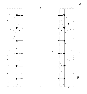
[0043] Embodiment 1: Drilling method Well wall (prefabricated in sections, with annular flange plates at both ends of the well wall)

[0044] The steel plate reinforced concrete shaft wall created by the present invention is mainly composed of a steel plate cylinder 1, a circumferential steel frame 2 (H-shaped steel), an inner vertical steel frame 3 (H-shaped steel), an outer vertical steel frame 4 (H-shaped steel), a diameter Composition of connecting piece 5 and concrete 6 (see Picture 1-1 and Figure 1-2 ).

Embodiment approach

[0046] (1) On the flange plate at the lower end of the shaft wall, the outer vertical steel frame 4 and the inner vertical steel frame 3 are arranged along different ring diameters (the ring spacing and circumferential spacing can be adjusted according to needs) and welded on the flange plate;

[0047] (2) Install and fix the steel arc section on the outer vertical steel frame 4, and form a closed circular steel frame 2 by welding or bolting; then install and fix the pre-bent curved steel frame on the inner vertical steel frame 3 , forming a closed steel tube 1 by welding;

[0048] (3) Utilize the radial connecting piece 5 to connect the steel plate cylinder 1 and the circumferential steel frame 2 to form a spatial structure;

[0049] (4) Install the flange plate at the upper end, and weld it firmly with the inner vertical steel frame, the outer vertical steel frame, and the steel plate cylinder;

[0050] (5) Install the outer formwork and supporting structure required for sh...

Embodiment 2

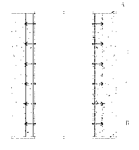
[0052] Embodiment 2: Drilling method Well wall (prefabricated in sections, with annular flange plates at both ends of the well wall)

[0053] The steel plate reinforced concrete well wall created by the present invention is mainly composed of a steel plate tube 1, a circumferential steel frame 2 (channel steel), an inner vertical steel frame 3 (channel steel), an outer vertical steel frame 4 (channel steel), a diameter Composition of connecting piece 5 and concrete 6 (see diagram 2-1 and Figure 2-2 ).

[0054] Implementation method: same as embodiment one.


PUM


Abstract

The invention discloses a steel plate and steel reinforced concrete well wall, which is mostly suitable for deep vertical shafts for bearing high ground pressure and high water pressure. A steel plate cylinder, an annular steel rib, inside vertical steel ribs, outside vertical steel ribs and radial connecting pieces are arranged and concrete is poured to form a cylindrical well wall. The steel plate cylinder and the annular steel rib are respectively positioned on the inner surface of the well wall and in the well wall, and are respectively fixed to the inside and outside vertical steel ribs; the steel plate cylinder and the annular steel rib are connected through the radial connecting pieces to form a spatial structure; and concrete is poured into an annular space formed by the steel plate cylinder and a well wall template or surrounding rock to coat the annular steel rib, the inside and outside vertical steel ribs and the like, and the cylindrical well wall structure is formed. The steel ratio on the inner side of the well wall is high, the concrete between the steel plate cylinder and the annular steel rib is positioned in a three-directional stress state, the compressive strength can be obviously improved, a core bearing area is formed, and the ultimate bearing capacity of the well wall is greatly improved. The steel plate and steel reinforced concrete well wall is used for building deep vertical shafts, the thickness of the well wall can be greatly reduced and the cost is reduced; and the steel plate and steel reinforced concrete well wall is reasonable in structure and easy and convenient to construct and has wide applicability.

Description

1. Technical field [0001] The invention relates to steel plate steel reinforced concrete well walls, especially suitable for deep shaft shafts in deep alluvium and water-rich rock formations in mine construction, such as shafts of common sinking, freezing, drilling and caisson methods. 2. Background technology [0002] With the development of deep mineral resources in my country, the depth of wellbore construction continues to increase, and the bearing capacity of the shaft wall has to be greatly increased to withstand the increasing deep ground pressure. For this reason, there are only two approaches: one is to improve the material strength and thickness of the well wall without changing the structure of the well wall; the other is to change the well wall structure. At present, the commonly used reinforced concrete wall structure is difficult to meet the needs of deep mine construction, while the cast iron or cast steel shaft walls, Chubin block shaft walls, and concrete ar...

Claims


Application Information

Patent Timeline
IPC IPC(8): E21D5/11
Inventor 王衍森杨维好杨然黄家会
Owner CHINA UNIV OF MINING & TECH
Why Eureka
Try Eureka