Function gradient concrete composite well wall and manufacturing method

A technology of functional gradient and production method, which is applied in earth-moving drilling, shaft equipment, wellbore lining, etc., can solve the problems such as the inability to effectively improve the ultimate bearing capacity of the well wall, the insufficient utilization of concrete material properties, and the uneven stress distribution on the well wall. , to achieve the effect of low concrete strength requirements, reduced material usage, and reduced shaft wall thickness

Inactive Publication Date: 2020-06-16
NORTH CHINA ELECTRIC POWER UNIV (BAODING)
View PDF7 Cites 5 Cited by
  • Summary
  • Abstract
  • Description
  • Claims
  • Application Information

AI Technical Summary

Problems solved by technology

When radial pressure acts on the outer edge of a traditional single-layer homogeneous shaft, the stress distribution in the well wall will be uneven, and a large tangential stress concentration will occur near the inner edge. If the thickness or strength of the well wall is not enough, it will occur destroy
In order to improve the ultimate bearing capacity of the shaft wall structure, one method adopted at this stage is to increase the wall thickness. However, when the shaft wall thickness increases to a certain limit, the tangential stress near the inner edge is difficult to be greatly reduced. That is, the ultimate bearing capacity of the borehole wall cannot be effectively improved
Another method is to increase the strength of concrete to increase the ultimate bearing capacity of the shaft wall, but this method does not fully utilize the properties of concrete materials
And these two kinds of methods have all increased the cost of shaft greatly, have increased the construction cost of project

Method used


Image

  • Function gradient concrete composite well wall and manufacturing method
  • Function gradient concrete composite well wall and manufacturing method
  • Function gradient concrete composite well wall and manufacturing method

Examples


Embodiment

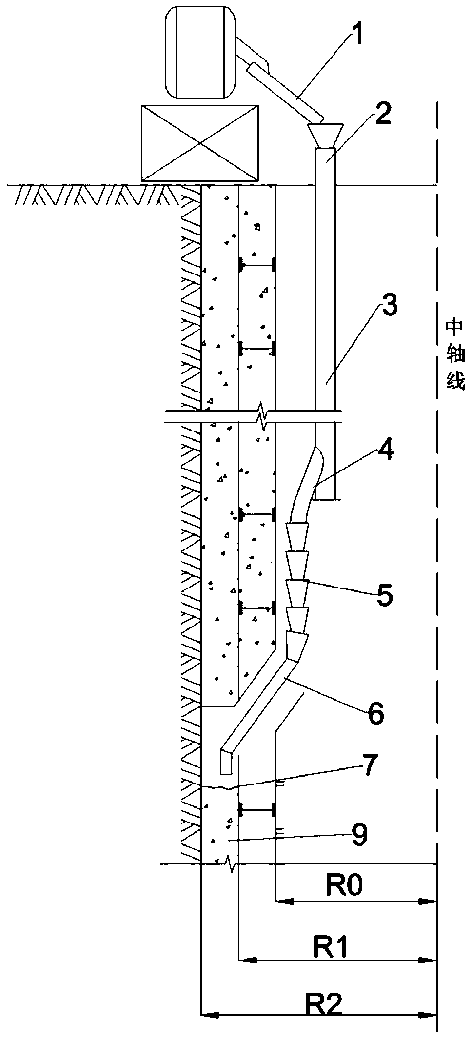
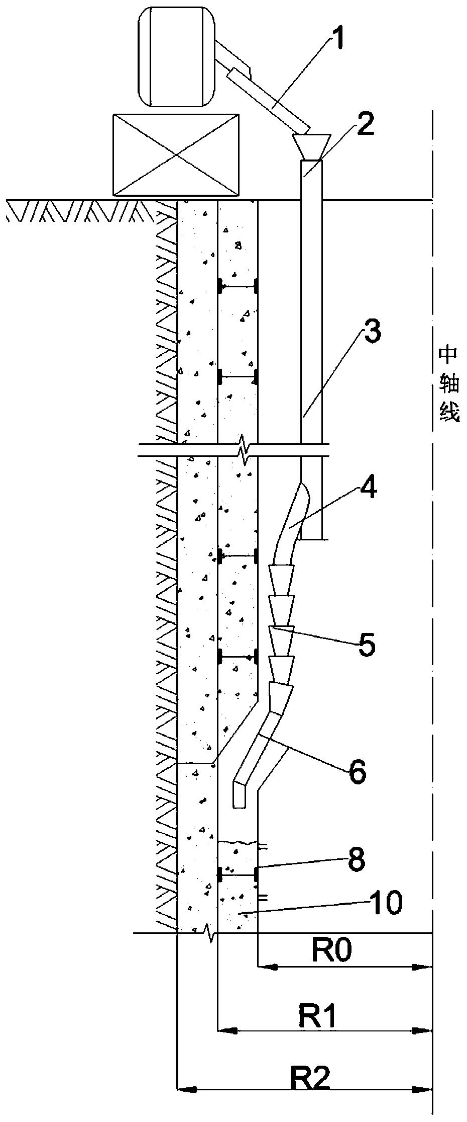
[0029] The specific manufacturing method of the cast-in-place double-layer functionally graded concrete composite well wall is to excavate a shaft with a radius of R2 at the construction site, and to select the inner formwork 7 of the outer well wall and the inner formwork 8 of the inner well wall with the radii of R1 and R0 respectively as The inner mold of the outer wellbore and the inner mold of the inner wellbore fix the two templates (such as Figure 1a , Figure 1b As shown), in order to ensure uniform thickness of the well wall, it is necessary to ensure that the central axes of the inner formwork 7 of the outer well wall and the inner formwork 8 of the inner well wall coincide as much as possible. Apply the release agent evenly on the outer surface of the inner mold, first as Figure 1a As shown, the outer layer of concrete 9 is poured through the chute 1, the funnel casing 2, the feeding pipe 3, the buffer 4, the hinged ash chute 5, and the ash guide pipe 6 to the gap ...


PUM


Abstract

The invention discloses a function gradient concrete composite well wall and manufacturing method and belongs to the technical field of vertical well construction. The function gradient concrete composite well wall is manufactured by adopting a prefabricating or cast-in-place manner. The function gradient concrete composite well wall comprises multiple layers of concrete well walls, wherein the concrete well walls are combined coaxially and closely, and elastic moduli of the concrete well walls are different. Damping material layers are arranged among the layers. All the well walls are arranged with different thicknesses. The concrete material performance is utilized fully, and the function gradient concrete composite well wall with the low requirement for concrete strength, small wall thickness and low project manufacture cost is manufactured. The elastic limit bearing capacity of a thick-wall cylinder is improved remarkably, and high-strength concrete does not need to be used. The well wall thickness is reduced, the material use amount is reduced, and the project manufacturing cost is reduced substantially.

Description

technical field [0001] The invention belongs to the technical field of shaft construction, and in particular relates to a functional gradient concrete composite shaft wall and a manufacturing method thereof. Background technique [0002] Shafts are commonly used in underground engineering, and are widely used in mineral mining, tunnel construction, water conservancy projects, etc. When radial pressure acts on the outer edge of a traditional single-layer homogeneous shaft, the stress distribution in the well wall will be uneven, and a large tangential stress concentration will occur near the inner edge. If the thickness or strength of the well wall is not enough, it will occur destroy. In order to improve the ultimate bearing capacity of the shaft wall structure, one method adopted at this stage is to increase the wall thickness. However, when the shaft wall thickness increases to a certain limit, the tangential stress near the inner edge is difficult to be greatly reduced. ...

Claims


Application Information

Patent Timeline
Patent Type & Authority Applications(China)
IPC IPC(8): E21D5/11E21D5/12
CPCE21D5/11E21D5/12
Inventor 张宁张雨辰吕爱钟陈旭光
Owner NORTH CHINA ELECTRIC POWER UNIV (BAODING)
Why Eureka
Try Eureka