

Heat transmission method and system for heat-pipe-type solar hot water system
A technology of solar water heating and transmission method, applied in solar heating systems, solar thermal energy, solar thermal power generation, etc., can solve the problems of difficult removal, low steam pressure, large heat loss, etc., and achieves wide application and reduces heat loss. Effect
- Summary
- Abstract
- Description
- Claims
- Application Information
AI Technical Summary
Problems solved by technology
Method used
Image

Examples
Embodiment 1
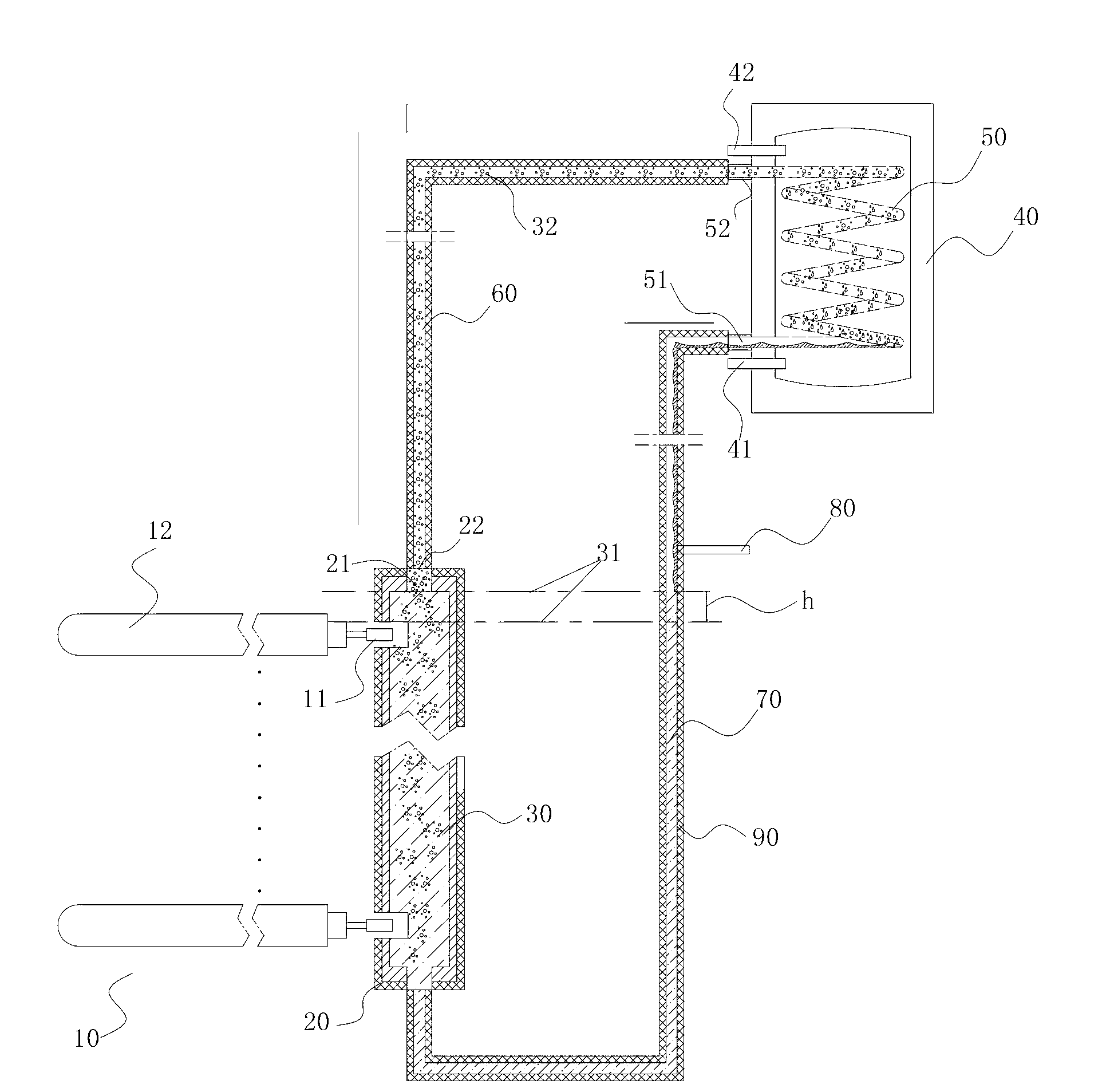
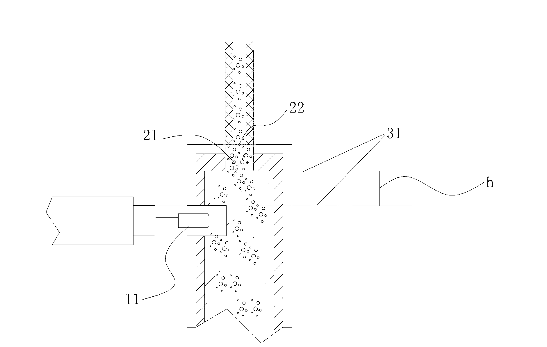
[0089] combine figure 1 The thermal energy transmission method of the heat pipe solar water heating system of the present invention will be described in detail. The thermal energy transfer method of the present invention specifically includes two processes:
[0090] Process 1, the process of collecting solar energy by the heat pipe type heat collecting unit 10 and converting the solar energy into heat energy; Through the extremely high heat collection efficiency of the heat pipe solar heat collection unit 10 , solar energy is collected and converted into heat energy inside the heat pipe. The heat energy is transferred to the heat energy transfer process through the heat exchange end 11 of the heat pipe type heat collection unit 10 .
[0091] Process 2, the heat energy converted by the heat collection unit 10 is transferred to the water tank 40 through the heat energy transmission system, and the heat energy transmission process of heating the low-temperature water in the wat...
Embodiment 2
[0125] The solar water heating system of the present embodiment is as figure 2 As shown, the working principle and effect of heat energy transmission in this embodiment are basically the same as those in Embodiment 1.
[0126] Specifically, in the embodiment, the sealed cycle heat energy transmission system adopts a vacuum system, and the air pressure in it is lower than atmospheric pressure, so that the heat exchange working medium 30 in it is more likely to boil, even in northern areas with low winter temperatures, or high altitude areas It can also be used normally. In the specific implementation process, a vacuum device can be installed on the steam channel 60 or the working fluid return channel 70. After the airtightness of the entire system is checked, the vacuum operation is performed first, and then the vacuum device is closed, and then the liquid is injected The device injects the heat exchange working medium 30, and finally seals the liquid injection device; it is ...
Embodiment 3
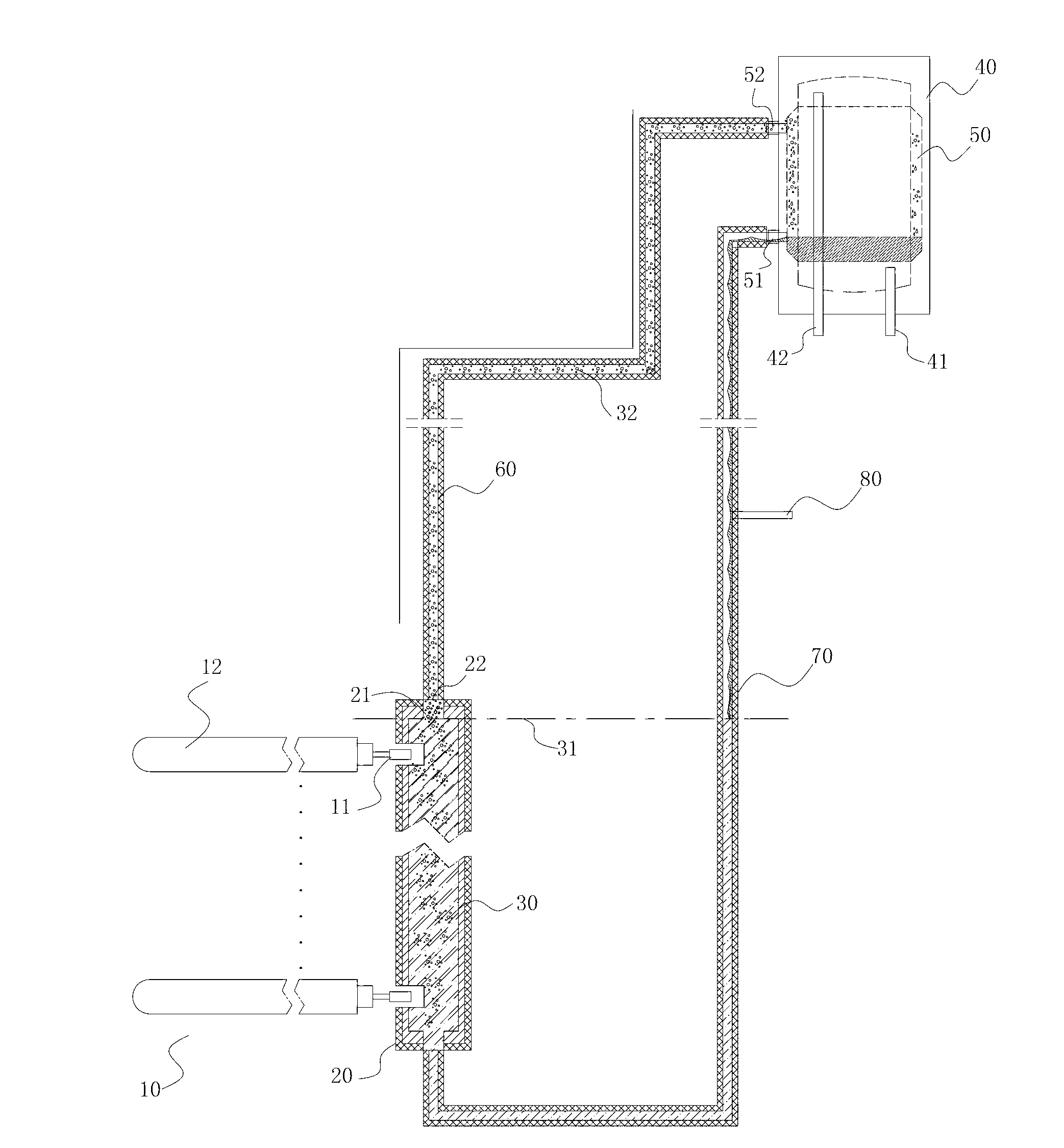
[0132]The solar water heating system of the present embodiment is as image 3 As shown, the working principle and effect of heat energy transmission in this embodiment are basically the same as those in Embodiment 1.
[0133] Such as image 3 As shown, the difference between this embodiment and the first embodiment is that the secondary heat exchanger 50 and the water tank 40 are horizontal coil structures. In this way, due to the existence of the coil structure, the contact area between the secondary heat exchanger 50 and the water tank 40 , that is, the heat exchange area increases, and the heat transfer efficiency in the water tank 40 also increases accordingly.
[0134] In this example, if image 3 As shown, the heat collection units 10 can be arranged in horizontal rows, and the heat exchange ends 11 of the heat collection units 10 are connected to the heat collectors 20 arranged vertically.
PUM
| Property | Measurement | Unit |
|---|---|---|
| Boiling point | aaaaa | aaaaa |
| Boiling point | aaaaa | aaaaa |
| Boiling point | aaaaa | aaaaa |
Abstract
Description
Claims
Application Information