Rotary road assembly of generalization slip-ring rotor

A slip ring rotor, a universal technology, applied in the direction of electrical components, rotating current collectors, current collectors, etc., can solve the problems of high processing difficulty, processing difficulty, signal interference, etc., to save processing procedures, improve matching accuracy, Guarantee the effect of stable transmission

Inactive Publication Date: 2013-05-01
中国船舶重工集团公司第七二三研究所
View PDF5 Cites 0 Cited by
  • Summary
  • Abstract
  • Description
  • Claims
  • Application Information

AI Technical Summary

Problems solved by technology

[0003] In the existing technology, when processing the insulating shaft of the slip ring rotor, it is necessary to dig a central hole and four U-shaped grooves in the circumferential direction for the long insulating shaft, which brings certain difficulties to the processing, especially to ensure that the central hole must be matched with the mandrel. makes processing more difficult
In addition, since there are only 4 U-shaped threading grooves on the insulating shaft, it cannot meet the requirements of various current signals, for example, the signal may be interfered due to the inability to separate the strong electric cable and the signal line

Method used


Image

  • Rotary road assembly of generalization slip-ring rotor
  • Rotary road assembly of generalization slip-ring rotor
  • Rotary road assembly of generalization slip-ring rotor

Examples


Embodiment Construction

[0026] The present invention will be described in detail below with reference to the accompanying drawings and examples.

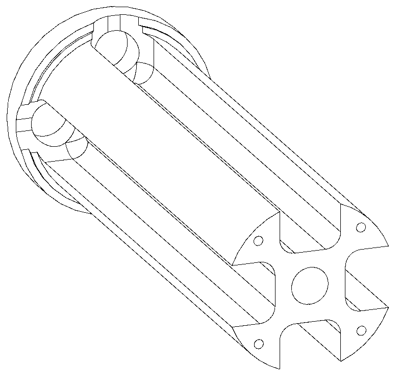
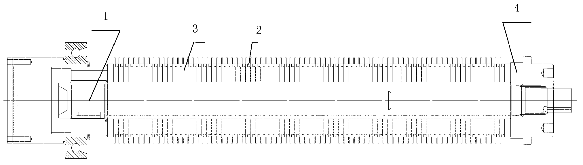
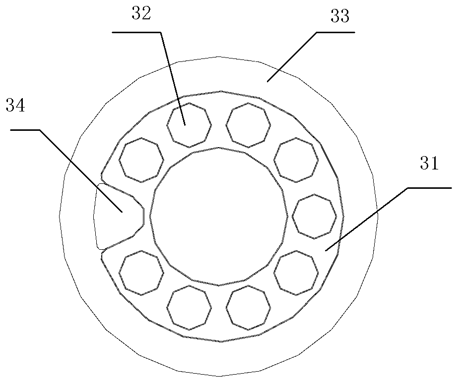
[0027] The invention provides a generalized slip ring rotor ring assembly, such as figure 2 As shown, it includes insulating ring 3 and metal ring 2. As shown in Figure 3 (a) and (b), the center of insulating ring 3 is processed with a center hole that matches the outer circle of mandrel 1 of the slip ring rotor. The outer side processes the annular boss, and the outer circle of the annular boss matches the inner circle of the metal ring 2; the ring between the outer circle of the bottom end of the annular boss 31 and the outer circle of the insulating ring 3 is used as a flash 33; A plurality of threading holes 32 of the same size are evenly opened in the circumferential direction; the number of threading holes 32 is determined according to the properties and types of the transmission current. When there are many types of current, different types of curr...


PUM


Abstract

The invention relates to a rotary road assembly of a generalization slip-ring rotor. The rotary road assembly comprises an insulating ring and a metal ring, wherein the insulating ring is of an integral structure formed by a circular flange and an annular boss; an excircle of the annular boss is matched with an incircle of the metal ring; and thread holes penetrating through the insulating ring are respectively and uniformly arranged in an upper surface of the annular boss along the periphery. An insulating shaft in the prior art is removed, and the functions of insulation and positioning of the insulating shaft are realized by adopting the insulating ring with a special structure to overlap, so that the manufacturing procedure for processing the insulation shaft is removed; only fit precision between the rotary road assembly assembled by the insulating ring and the metal ring and a central spindle needs to be ensured, so that the fit precision is also improved; the thread holes are processed in the insulating ring, so that cable conductors of different types can be distributed into the different thread holes, and the insulation between the cable conductors of different types is ensured; and a fan-shaped hole is processed in the insulating ring, and an inner wall of the metal ring is exposed, so that a cable can be conveniently welded on the inner wall of the metal ring.

Description

technical field [0001] The invention relates to the technical field of slip ring structure design, in particular to a generalized ring track assembly of a slip ring rotor. Background technique [0002] At present, the structural design of slip rings tends to be more and more integrated and miniaturized, and the requirements for the rotor ring are getting faster and higher. Slip ring rotors generally include metal rings, insulating rings, mandrels and some fixed parts such as locking parts, such as figure 1 As shown, it is the insulating shaft in the existing slip ring rotor, with 4 U-shaped threading grooves in the circumferential direction, and a central hole matching the mandrel in the middle. A plurality of metal rings and insulating rings are placed on the outer circle of the insulating shaft at intervals, and finally the front end of the insulating shaft is locked with a locking piece to form a slip ring rotor. A flash edge is processed on the outer circle of the insu...

Claims


Application Information

Patent Timeline
Patent Type & Authority Applications(China)
IPC IPC(8): H01R39/08H01R39/10
Inventor 刘一鸣沙旭南周晖
Owner 中国船舶重工集团公司第七二三研究所
Why Eureka
Try Eureka