Network voltage disturbance generating device and control method thereof

A technology for generating device and grid voltage, which is applied in circuit devices, output power conversion devices, electrical components, etc., and can solve difficult three-phase asymmetrical faults, accurate simulation of faults, complex inverter control strategies, and poor economy. problems, to achieve the effect of convenient device capacity, small harmonics, and expansion of device capacity

Active Publication Date: 2013-05-01
STATE GRID HUBEI ELECTRIC POWER RES INST +1
View PDF2 Cites 49 Cited by
  • Summary
  • Abstract
  • Description
  • Claims
  • Application Information

AI Technical Summary

Problems solved by technology

[0003] 1. Most voltage disturbance generating devices use a topology structure in which three-phase half-bridge rectifiers and three-phase half-bridge inverters are connected back to back. This structure is not easy to achieve different three-phase voltages due to the possibility of mutual influence between the output three-phase voltages. Accurate simulation of symmetrical faults, and its inverter-side control strategy is more complex
[0004] 2. Part of the voltage disturbance generating device adopts a topology structure of three single-phase AC-DC converters connected in parallel. Although this structure can better realize the required simulation functions, it uses more devices and is not economical.

Method used


Image

  • Network voltage disturbance generating device and control method thereof
  • Network voltage disturbance generating device and control method thereof
  • Network voltage disturbance generating device and control method thereof

Examples


Embodiment Construction

[0026] The technical solutions in the present invention will be clearly and completely described below in conjunction with the accompanying drawings in the present invention.

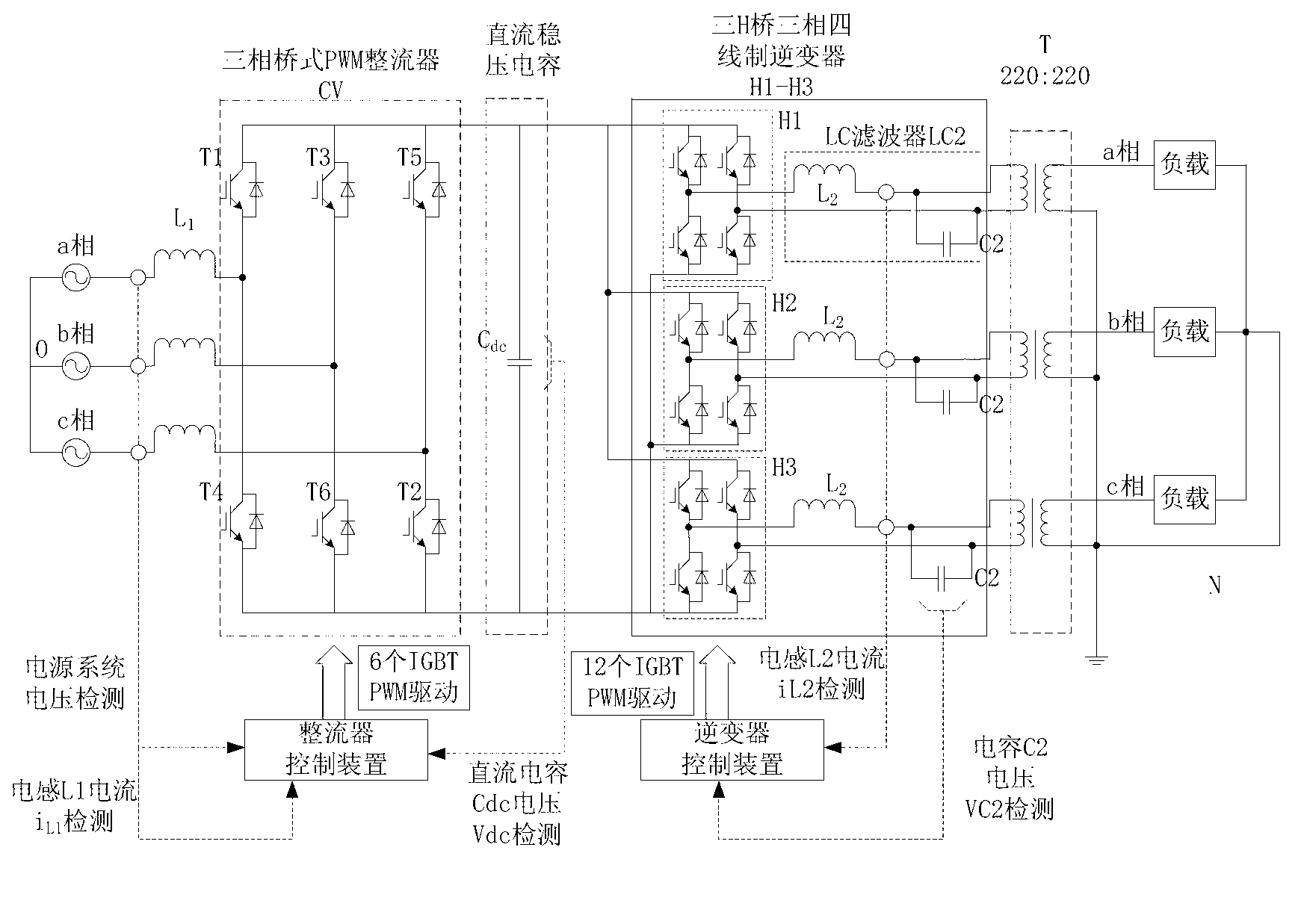
[0027] Please refer to figure 1 The power grid voltage disturbance generating device of the present invention includes an L-shaped filter L1, a three-phase bridge PWM rectifier (CV) controlled by voltage and current double loops, a DC capacitor Cdc, and a three-H bridge three-phase four-wire PWM inverter controlled by voltage and current double loops device (H1-H3), inverter output side LC filter LC2, isolation transformer T. The AC side of the three-phase bridge PWM rectifier is connected to the grid through an L-shaped filter L1, the DC side of the three-phase bridge PWM rectifier is connected in series with the DC side of the three-phase four-wire PWM inverter of the three-H bridge, and the three-phase bridge PWM A DC capacitor Cdc is also connected in parallel between the DC side of the rectifier a...


PUM


Abstract

The invention provides a network voltage disturbance generating device, which comprises a three-phase bridge type PWM (Pulse Width Modulation) rectifier and a three-H-bridge three-phase four-wire-system PWM inverter, wherein the alternating current side of the rectifier is connected with an electric network through an L type filter; the direct current side of the rectifier is connected in series with the direct current side of the three-H-bridge three-phase four-wire-system PWM inverter; an LC filter is connected to the alternating current side of the three-H-bridge three-phase four-wire-system PWM inverter; the output end of the LC filter is connected with an isolation transformer; and the secondary side of the isolation transformer is connected with a load. The invention further provides a control method suitable for the device. Due to the adoption of the device provided by the invention, the simulation of a network voltage amplitude, frequency disturbance and an electric network harmonic phenomenon can be realized, bilateral flow of energy can be realized, and active energy transmitted by tested solar-powered grid-connected equipment is fed back to the electric network; and the control method is easy and convenient to implement, and a target reference value can be accurately tracked; and moreover, quick response and small steady-state errors are realized, so that electric network disturbance can be simulated accurately.

Description

technical field [0001] The invention relates to the technical field of electrical equipment and electrical engineering, in particular to a grid voltage disturbance generating device and a control method thereof. Background technique [0002] With the massive application of new energy, the micro-grid composed of new energy-based distributed power generation is developing rapidly, and the grid-connected converter, as a bridge connecting the large power grid and the micro-grid, is also popularized. Whether the grid-connected converter can work stably directly affects the safety of the distributed generation system. How to evaluate the performance of the grid-connected converter has become an important research topic. Most of the current voltage disturbance generation platforms use back-to-back dual PWM AC-DC converters for simulation, which have the following defects: [0003] 1. Most voltage disturbance generating devices adopt a topology structure in which three-phase half-b...

Claims


Application Information

Patent Timeline
Patent Type & Authority Applications(China)
IPC IPC(8): H02J3/00H02M5/458H02M7/219H02M7/797H02M7/5387
Inventor 丁凯夏勇军徐华安孙建军刘飞
Owner STATE GRID HUBEI ELECTRIC POWER RES INST
Why Eureka
Try Eureka