Turning fixture for gleason spiral bevel gear

A gear turning and arc tooth technology, which is applied in turning equipment, turning equipment, positioning devices, etc., can solve the problems of poor control of the back and forth movement of the grinding wheel, low efficiency, and difficulty in production, and meet the requirements of ensuring consistency and shape and position error. As well as gear accuracy requirements, avoiding benchmark conversion errors, and improving production efficiency

Inactive Publication Date: 2013-05-08
JIANGSUSNGCHI GROUP
View PDF0 Cites 4 Cited by
  • Summary
  • Abstract
  • Description
  • Claims
  • Application Information

AI Technical Summary

Problems solved by technology

[0002] Spiral bevel gears such as figure 1 As shown, the surface hardness of the spiral bevel gear is HRC58-62, the pitch circle of the gear is 0.06 mm to the circular runout of the inner hole, the large plane T is 0.025 mm to the circular runout of the inner hole, the flatness is 0.015 mm, and the roughness requirement is Ra1.6; Its special structure is that there is an internal spline at the front of the inner hole φ58.50.0190, the minor diameter of the internal spline is φ55.6, and the length of the relief groove φ59 between the two is only 5 mm. According to the traditional grinding method For processing, first grind the inner hole φ58.50.019 0, and then polish the T surface; the processing is time-consuming and laborious, mainly because the length of the relief groove φ59 is only 5 mm, and the back and forth movement of the grinding wheel is not easy to control, and each shift can only grind more than 30 pieces , the efficiency is not high, due to the large quantity of each batch and the short delivery time, it brings certain difficulties to production

Method used


Image

  • Turning fixture for gleason spiral bevel gear
  • Turning fixture for gleason spiral bevel gear

Examples


Embodiment Construction

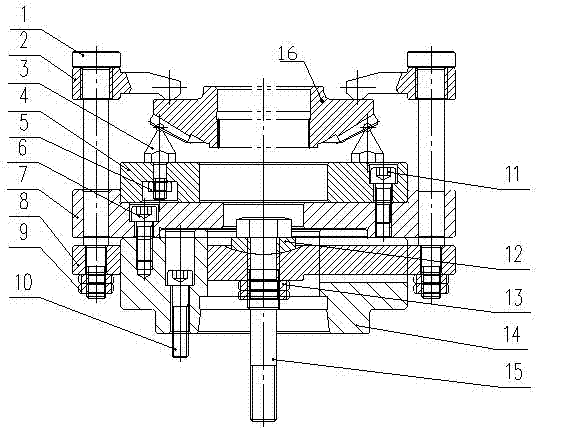
[0010] The present technology will be further described below through the embodiments in conjunction with the accompanying drawings.

[0011] Such as figure 2 As shown, the fixture is connected with the spindle of the CNC lathe CK7516 by the fixture seat 14 through the screw 10, and the fixture body 7, the support plate 4, and the positioning ball 3 are connected into one body with the screw 11 and the nut 5 and connected to the fixture seat 14 by the screw 6 and connected with the machine tool. The main shaft forms a fixed rotating body, which ensures that the support plate is consistent with the center of rotation of the main shaft of the machine tool;

[0012] The pressing plate 2 is mounted on the pull rod 1 and can rotate freely through threaded connection, and the pull rod 1 is fixed on the fork plate 8 through a round nut 9 to form a movable adjustment body that can move up and down.

[0013] The movable slider 12 is mounted on the central screw 15 and connected to th...


PUM

PropertyMeasurementUnit
hardnessaaaaaaaaaa

Abstract

The technology provides a turning fixture for an arc-teeth cone gear. The turning fixture for the Gleason spiral bevel gear can be connected to a lathe and can carry out turn an inner hole and a plane of the Gleason spiral bevel gear to improve the processing efficiency and ensure the processing quality. The turning fixture for the Gleason spiral bevel gear comprises a clamp base used for being connected with a spindle, a clamp is fixed on the clamp arc-teeth cone gear base, and a bearing plate is arranged on the clamp; at least three positioning balls, evenly located on the circumferential direction of the Gleason spiral bevel gear, are arranged on the bearing plate. The Gleason spiral bevel gear is pressed tightly on the positioning balls by three pressing plates sleeved on three pulling bars. Lower ends of the pulling bars are connected with a fork-shaped plate through the clamp; a spherical pair is formed by a center portion of the fork-shaped plate and a movable sliding block; a center screw rod is arranged on the movable sliding block to be connected to a spindle oil cylinder of the lathe; and the pressing plates are connected with the pulling bars by screw pairs.

Description

technical field [0001] The technology relates to a tool for turning a spiral bevel gear. Background technique [0002] Spiral bevel gears such as figure 1 As shown, the surface hardness of the spiral bevel gear is HRC58-62, the pitch circle of the gear is 0.06 mm to the circular runout of the inner hole, the large plane T is 0.025 mm to the circular runout of the inner hole, the flatness is 0.015 mm, and the roughness requirement is Ra1.6; Its special structure is that there is an internal spline at the front of the inner hole φ58.50.0190, the minor diameter of the internal spline is φ55.6, and the length of the relief groove φ59 between the two is only 5 mm. According to the traditional grinding method For processing, first grind the inner hole φ58.50.019 0, and then polish the T surface; the processing is time-consuming and laborious, mainly because the length of the relief groove φ59 is only 5 mm, and the back and forth movement of the grinding wheel is not easy to contr...

Claims


Application Information

Patent Timeline
Patent Type & Authority Applications(China)
IPC IPC(8): B23Q3/12B23B5/00
Inventor 唐雪峰张汉明
Owner JIANGSUSNGCHI GROUP
Why Eureka
Try Eureka