Energy dissipation type debris flow check dam combined draining and guiding and blocking

A technology for retaining sand dams and debris flow, applied in dams, buttress dams, marine engineering, etc., it can solve the problems of limited storage capacity of retaining dams, loss of debris flow retaining effect, and silting, so as to reduce kinetic energy and improve roughness. , the effect of preventing structural blockage

Inactive Publication Date: 2013-05-08
INST OF MOUNTAIN HAZARDS & ENVIRONMENT CHINESE ACADEMY OF SCI
View PDF10 Cites 19 Cited by
  • Summary
  • Abstract
  • Description
  • Claims
  • Application Information

AI Technical Summary

Problems solved by technology

However, these existing sand retaining dams all adopt the full retaining mode, mainly relying on the storage capacity of the dam itself to produce retaining effect on the debris flow
Due to the abundance of loose matter in debris flows in many areas, especially in earthquake-stricken areas, it is difficult to accurately predict the scale and frequency of debris flows, and the storage capacity of retaining dams is often limited. A large debris flow may cause it to be silted quickly, thus Loss of blocking effect on subsequent debris flow

Method used


Image

  • Energy dissipation type debris flow check dam combined draining and guiding and blocking
  • Energy dissipation type debris flow check dam combined draining and guiding and blocking
  • Energy dissipation type debris flow check dam combined draining and guiding and blocking

Examples


Embodiment 1

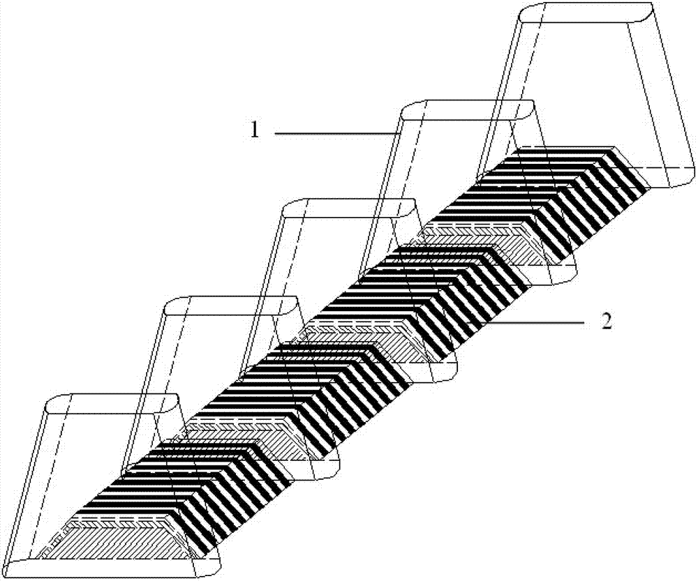
[0030] Such as figure 1 , figure 2 , image 3 , Figure 4 , Figure 5 , Figure 6 , Figure 7 shown. The drainage area of ​​a debris flow ditch is 0.5km 2 , the channel width is 20m, and the debris flow channel-bed gradient is 20%, at P 2% Under the design standard, the flow rate of debris flow is 20m 3 / s. In order to control debris flow disasters, it is planned to build a debris flow sand retaining dam combined with energy dissipation type drainage and blocking in the debris flow channel.

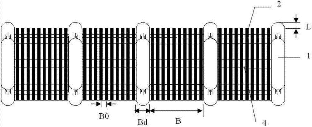
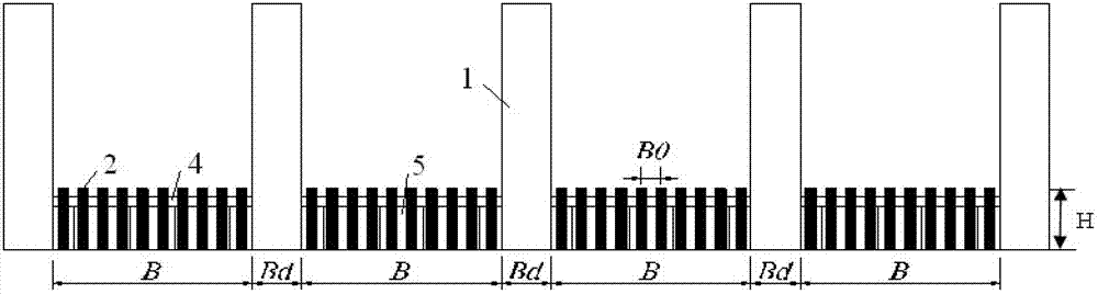
[0031] The sand control dam includes a dam body foundation and a dam body body located on the dam body foundation; the dam body body includes 12 reinforced concrete buttresses 1 distributed at certain intervals, and 1 of every two buttresses is provided with Horizontal grid 2. Due to the large slope of the ditch bed, the potential energy of the debris flow is large, and the debris flow has a strong ability to transport boulders and a high flow rate. In order to increase the bl...

Embodiment 2

[0033] Such as figure 1 , figure 2 , image 3 , Figure 4 , Figure 5 , Figure 6 , Figure 7 shown. The drainage area of ​​a debris flow ditch is 3.5km 2 , the channel width is 50m, and the debris flow channel bed ratio is 6%, at P 2% Under the design standard, the flow of debris flow is 60m 3 / s. In order to control debris flow disasters, it is planned to build a debris flow sand retaining dam combined with energy dissipation type drainage and blocking in the debris flow channel.

[0034]The sand control dam includes a dam body foundation and a dam body body located on the dam body foundation; the dam body body includes 14 reinforced concrete buttresses 1 distributed at certain intervals, and every two buttresses are provided with Horizontal grid 2. Due to the small gradient of the ditch bed, the wide watershed, the low discharge potential energy of the debris flow, the low flow velocity of the debris flow, and the weak ability of the debris flow to carry boulder...


PUM


Abstract

The invention discloses an energy dissipation type debris flow check dam combined draining and guiding and blocking. The check dam comprises a dam body foundation and a dam body main body arranged above the dam body foundation, wherein the dam body main body comprises a plurality of buttresses distributed at intervals, a horizontal grille is arranged between each two buttresses, the buttresses extend towards upstream compared with the horizontal grilles, and the height H of the horizontal grilles above ground is in the range of from 0.5 to 1.0 m. The horizontal grilles are hollow, and drain holes are formed in the horizontal grilles and provided with transverse beams and longitudinal beams for supporting. Compared with the prior art, the buttresses are used for supporting the dam body and blocking coarse grain; drain holes are used for draining and guiding water of debris flow passing through the check dam, destroying constitutive property of the debris flow, and avoiding clogging of constitutive property; the horizontal grilles are used for conducting energy dissipation type debris draining and guiding, improving discharge capacity of the dam body, enabling the whole check dam not prone to clogging, improving capacity of resisting secondary debris flow after debris flow discharging once, and meanwhile safety of downstream can be endangered.

Description

technical field [0001] The invention relates to a mud-rock flow prevention and control technology, in particular to a mud-rock flow sand retaining dam based on a buttress block, thick row and fine row, and a horizontal grille energy dissipation and row. Background technique [0002] Debris flow has a much higher bulk density than water flow, and its fluid binary structure containing clastic soil has special characteristics, such as high inertia, strong transport force, and huge impact force. The strong erosion produced by the debris flow movement leads to drastic changes in the ditch bed, causing the bottom of the ditch bed and the collapse of the ditch bank, which increases the source of solid materials to replenish the debris flow and increases the damage of the debris flow. , water canals, electricity, communication lines and other infrastructure, as well as farmland, forests and other serious damage. Therefore, the development of sand check dams that can effectively blo...

Claims


Application Information

Patent Timeline
Patent Type & Authority Applications(China)
IPC IPC(8): E02B7/14E02B8/06
Inventor 邹玉华陈晓清
Owner INST OF MOUNTAIN HAZARDS & ENVIRONMENT CHINESE ACADEMY OF SCI
Why Eureka
Try Eureka