Centrifugal pressure plate automatic clutch
An automatic clutch and centrifugal technology, applied in the direction of automatic clutch, clutch, mechanical equipment, etc., can solve the problems of increased cost, unsuitable application, inability to transmit load, etc., to achieve the effect of easy manufacture or transformation, favorable for promotion and implementation, and convenient use.
- Summary
- Abstract
- Description
- Claims
- Application Information
AI Technical Summary
Problems solved by technology
Method used
Image
Examples
Embodiment 1
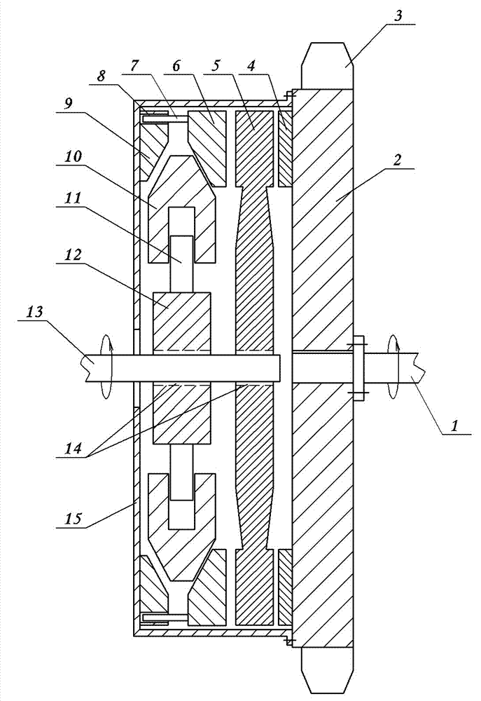
[0015] Embodiment 1: see figure 1 , the first centrifugal pressure plate automatic clutch, including the pressure plate 15, the driving part 12, the centrifugal body 10 and the driven part 2 and so on. The rotating shaft 13 of the driving part is connected to the rotating shaft of the power machine (such as an engine), and the driven part 2 is connected to the load through transmission. The driven part 2 can be connected to the load directly or through mechanisms such as pulleys. figure 1 The load in is the flywheel 3 integrated with the follower 2. A radial guide structure is set between the centrifugal body 10 and the active part 12, the specific structure is as figure 1 As mentioned above, a radial guide rod 11 is provided on the active member 12, and a corresponding radial guide groove is provided on the centrifuge body 10, and the two are matched and installed. In addition, a friction disc 5 is provided, and the friction disc 5 is installed on the rotating shaft 13 of t...
Embodiment 2
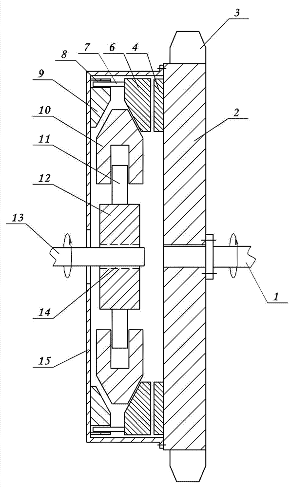
[0016] Example 2: see figure 2 , the second centrifugal pressure plate automatic clutch, including a pressure plate 15, a driving part 12, a centrifugal body 10 and a driven part 2, the rotating shaft 13 of the driving part is connected with the rotating shaft of the power machine, the driven part 2 is connected with the load transmission, and the driven part Part 2 is connected to the load transmission, and the driven part 2 can be connected to the load directly or through mechanisms such as pulleys. figure 2 The load in is the flywheel integrated with the follower. A radial guide structure is set between the centrifugal body 10 and the active part 12, the specific structure is as figure 2 As mentioned above, a radial guide rod 11 is provided on the active member 12, and a corresponding radial guide groove is provided on the centrifuge body 10, and the two are matched and installed. The driving member 12 is splined to the rotating shaft 13 of the driving member. The pre...
PUM
 Abstract
Description
Claims
Application Information
 - R&D
- Intellectual Property
- Life Sciences
- Materials
- Tech Scout
- Unparalleled Data Quality
- Higher Quality Content
- 60% Fewer Hallucinations
Browse by: Latest US Patents, China's latest patents, Technical Efficacy Thesaurus, Application Domain, Technology Topic, Popular Technical Reports.
© 2025 PatSnap. All rights reserved.Legal|Privacy policy|Modern Slavery Act Transparency Statement|Sitemap|About US| Contact US: help@patsnap.com


