
Vacuum heat insulation heat fluid energy-saving running pipeline

A technology for vacuum heat insulation and transportation pipelines, which is applied in the direction of heat insulation protection pipelines, heat preservation, pipeline protection, etc. It can solve the problems of high heat loss rate, large amount of heat loss, low heat utilization rate, etc., and achieve the goal of reducing operating costs Effect

Inactive Publication Date: 2013-05-08
沈双喜 +1
View PDF6 Cites 12 Cited by
  • Summary
  • Abstract
  • Description
  • Claims
  • Application Information

AI Technical Summary

Problems solved by technology

[0003] The invention provides a vacuum heat insulation heat preservation energy-saving heat fluid delivery pipeline, in order to solve the problems of relatively large single (double) pass heat loss, high heat loss rate and low heat utilization rate of the existing delivery pipeline

Method used


Image

  • Vacuum heat insulation heat fluid energy-saving running pipeline

Examples


Embodiment Construction

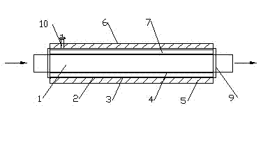
[0013] refer to figure 1 , an energy-saving conveying pipeline for vacuum heat-insulating thermal fluid, comprising an inner fluid pipe and an outer casing steel pipe, wherein the inner fluid pipe 1 is set in an outer outer steel pipe 2 . The specific package method is as follows: on the outer wall of the inner fluid pipe 1, a perforated circular plate with an inner diameter and an outer diameter respectively matched with the outer diameter of the inner fluid pipe 1 and the inner diameter of the outer jacket steel pipe 2 is installed, and at the same time, a certain length of the inner fluid pipe The heads of both ends of the outer jacket steel pipe 2 are to be welded and sealed, that is, the two ends of the outer jacket steel pipe 2 are welded and sealed by the head plate 9 so that a vacuum insulation layer 7 is formed between the two pipes, so that the outer jacket steel pipe 2 and the outer jacket steel pipe 2 are welded and sealed. The inner fluid pipe 1 is made as a whole...


PUM


Abstract

Provided is a vacuum heat insulation heat fluid energy-saving running pipeline. The vacuum heat insulation heat fluid energy-saving running pipeline comprises an inner fluid pipe and a shell steel pipe, the inner fluid pipe is arranged in the shell steel pipe in a sleeved mode, the two ends of the shell steel pipe is sealed by an end sealing plate and a vacuum heat insulation layer is formed between the two pipes, and the vacuum heat insulation layer is communicated with a sealed valve. By utilizing a triple heat insulation structure, heat energy radiation loss and cold coagulation in a steam, hot water transportation process are reduced, and the problems of relatively large single (double) way heat loss, high heat loss rate and low heat utilization efficiency of an existing running pipeline are reduced.

Description

technical field [0001] The invention relates to the technical field of energy conservation and environmental protection, in particular to a thermal insulation pipeline, in particular to a vacuum thermal insulation thermal fluid energy-saving transportation pipeline. Background technique [0002] At present, in industrial enterprises that use steam and hot water in production, and urban central heating and heating projects, one of the pipelines is wrapped with a thermal fluid steel pipe frame outer insulation sleeve and wrapped with glass cloth, and the other is made of high-density polyethylene outer protection pipe, polyurethane hard The mass foam is composed of an insulation layer and a thermal fluid steel pipe, and the three are combined into a tight whole; although this structure can play a certain heat insulation effect, the loss of heat energy during the transportation process is still about 10% to 35%. The conveying radius is only about 8km. Contents of the inventio...

Claims


Application Information

Patent Timeline
IPC IPC(8): F16L59/02F16L59/065F16L59/08
Inventor 沈双喜范利宁
Owner 沈双喜
Learn More