Heat exchanger

A technology of heat exchangers and fins, applied in the field of heat exchangers, can solve the problems of increased air flow resistance and reduced heat exchange performance, and achieve the effects of improved fin efficiency, easy manufacturing and management, and prevention of hole clogging

Active Publication Date: 2013-05-08
T RAD CO LTD
View PDF7 Cites 11 Cited by
  • Summary
  • Abstract
  • Description
  • Claims
  • Application Information

AI Technical Summary

Problems solved by technology

It can be seen that the flow resistance of the air flow increases due to the a

Method used


Image

  • Heat exchanger
  • Heat exchanger
  • Heat exchanger

Examples


Embodiment Construction

[0050] Next, embodiments of the present invention will be described based on the drawings.

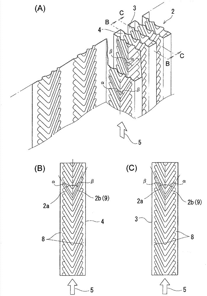
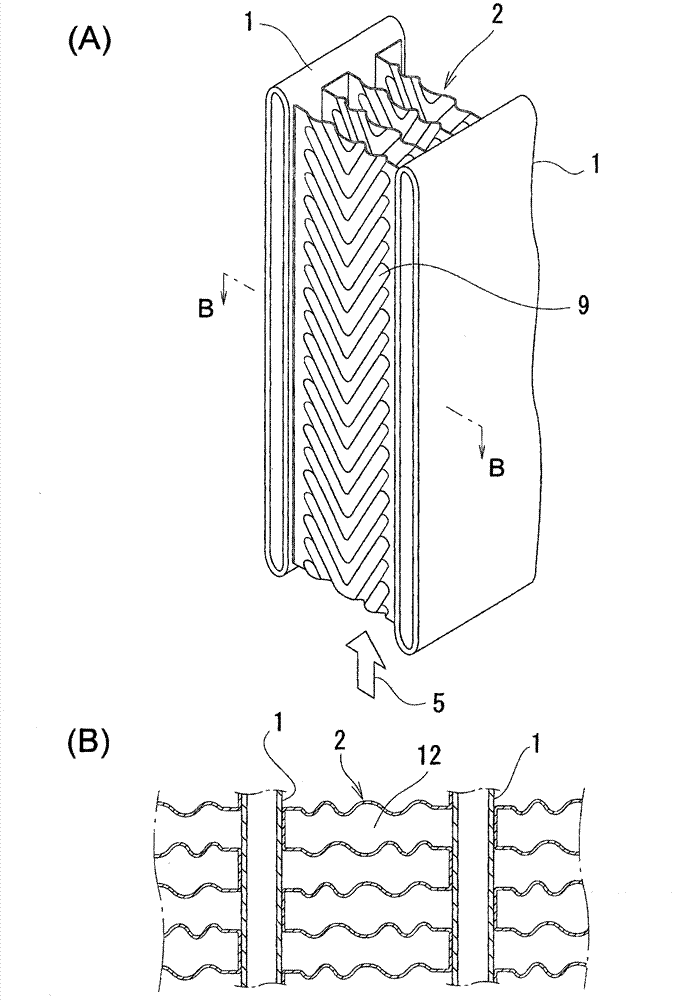
[0051] figure 1 It is explanatory drawing of the corrugated fin of this invention, (A) is its perspective schematic view, (B) is the top view of the 1st plane 4 of (A), (C) is the top view of the 2nd plane 3 of (A). in addition, figure 2 (A) is a perspective view of main parts of the heat exchanger, and (B) is a cross-sectional view thereof viewed along the direction of B-B.

[0052] Such as figure 2 As shown in (A), in the heat exchanger of this example, corrugated fins 2 are fixed in contact with each other between a plurality of parallel flat tubes 1 . In this example, the entire fin 2 is bent into a rectangular wave shape, and the bent top and bottom of the fin 2 are soldered and fixed to the flat tube 1 . And, there is a flat first plane 4 and a second plane 3 facing it between the top and the valley, and on each of the planes 3, 4, there are a plurality of parallel planes ...


PUM


Abstract

The invention provides a heat exchanger. A plurality of V-shaped strip portions (9) are parallelly arranged on surfaces of fins of the heat exchanger, dust or coal and the like are difficult to attach to each portion of the fins (2), and the thermal efficiency is good. In a first plane (3) of each fin (2), a pair of inclined strip portions (2a and 2b) forms a V shape, one inclined strip portion in the pair of inclined strip portions (2a and 2b) is configured at an inclined angle (alpha) towards a front side in a direction opposite to the circulating direction of gases, the other inclined strip portion in the pair of inclined strip portions (2a and 2b) is configured at an inclined angle (beta) towards a back side in a direction opposite to the circulating direction of the gases, and thereby the inclined strip portions (2a and 2b) form a right and left asymmetrical angle. Besides, a right and left asymmetrical angle in a second plane (4) opposite to the first plane (3) is opposite to that of the first plane (3) in a direction relative to the circulating direction of the gases.

Description

technical field [0001] The present invention relates to the fins of heat exchangers, and in particular to the heat exchangers used in places with a lot of sand and dust or in which the exhaust gas of an engine flows, and the heat of particulate matter such as dust is difficult to adhere to the surface of the fins. switch. Background technique [0002] The most effective method for improving the performance of the heat exchanger is to form multiple louvers cut into the surface of the fins. [0003] However, in a heat exchanger used in a dusty place or a heat exchanger through which exhaust gas from an engine flows, clogging occurs in the louver, and the fin efficiency rapidly decreases. [0004] Here, various fins are known in which louver fins are modified to form corrugated or convex shapes on the surface of the fins. [0005] As an example, the following patent document 1 is proposed. its like Figure 9 As shown in (A) and (B), a plurality of W-shaped convex lines and c...

Claims


Application Information

Patent Timeline
IPC IPC(8): F28F1/30F02M25/07F02M26/29F02M26/31
CPCY02T10/121Y02T10/12
Inventor 中野公昭佐佐木洁秋泽宏一小野纯八谷敏克佐久间哲渡濑惠梨子
Owner T RAD CO LTD
Why Eureka
Try Eureka