Energy-saving inverter test circuit and control method

A technology of test circuit and inverter circuit, which is applied in the direction of instruments, measuring electricity, measuring electric variables, etc., can solve the problems of not saving energy, and achieve the effect of simple wiring, remarkable energy saving effect, and avoiding energy consumption

Active Publication Date: 2013-05-08
XINFENGGUANG ELECTRONICS TECH CO LTD
View PDF8 Cites 11 Cited by
  • Summary
  • Abstract
  • Description
  • Claims
  • Application Information

AI Technical Summary

Problems solved by technology

[0003] At present, the most common test method used in the full load test is that the inverter drives the motor, and the motor drives the generator for loading. The electric energy generated by the generator is either consumed through resistance heating, or fed back to the power grid through the invert

Method used


Image

  • Energy-saving inverter test circuit and control method
  • Energy-saving inverter test circuit and control method
  • Energy-saving inverter test circuit and control method

Examples


Embodiment Construction

[0031] The present invention will be further described below in conjunction with the accompanying drawings and embodiments.

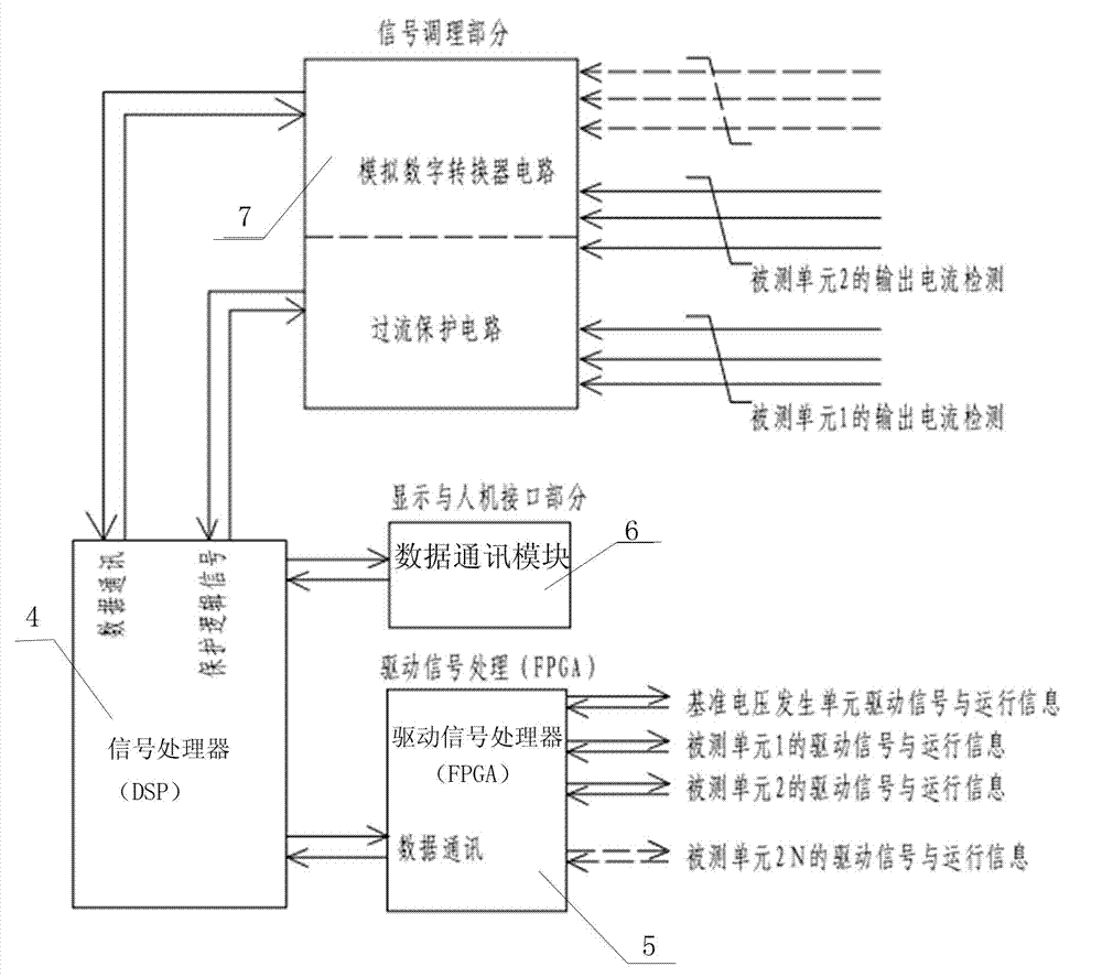
[0032] The energy-saving inverter test circuit of the present invention is composed of a reference voltage generating unit 1, a reactor 2, a tested inverter unit 3 and a controller unit. The controller unit has the functions of signal acquisition, data calculation and control output. The voltage generating unit 1 is used for generating voltage signals with adjustable frequency and amplitude. Such as figure 1The circuit schematic diagram of the controller unit is shown as shown, which includes a signal processor 4, a drive signal processor 5, a data communication module 6, an analog-to-digital conversion circuit 7 and an overcurrent protection circuit; the signal processor is composed of a DSP chip, Realize the main acquisition and control functions. The driving signal processor 5 is connected with the signal processor 4, and can be formed by FPGA, and...


PUM


Abstract

The invention discloses an energy-saving inverter test circuit which is characterized by comprising a reference voltage generating unit, an electric reactor, 2N tested inverter units and a controller unit. Power of inverters in the same group of tested inverter units is equal. The inverter circuit can be composed of part insulated gate bipolar translators (IGBT) which is capable of being closed. The controller unit controls two tested inverter units in the same group, one tested inverter unit works in a sending inductive reactive state, and the other one tested inverter unit works in a sending equivalent capacitive reactive state. The N is a positive integer. The control method comprises the steps of a) connecting the tested inverters, b) detecting signal connection, c) charging a bus, and d) outputting voltage with the same frequency and the same phase, and achieving reactive power hedging. According to the energy-saving inverter test circuit, a connecting manner is rapid and convenient to achieve, a total power test of a high-power inverter unit can be achieved in a condition that a preceding stage input capacity is small, electric energy and test cost are effectively saved, and the test manner is efficient and energy-saving.

Description

technical field [0001] The present invention relates to an energy-saving inverter test circuit and control method, more specifically, to an energy-saving inverter test circuit and control method in which two tested inverter units in the same group perform reactive power hedging Control Method. Background technique [0002] With the increasing development and maturity of power electronic technology, inverter products of various voltage levels are more and more used in various occasions and fields. In order to ensure that the products are reliable during release and user use, manufacturers must Carry out detailed performance, function and environmental tests on inverter products. The full load test is the most important one. The main tests that can be assessed are temperature rise test, loss test, efficiency, voltage stress, current stress and over-current capability. . [0003] At present, the most common test method for full-load testing is that the inverter drives the mo...

Claims


Application Information

Patent Timeline
IPC IPC(8): G01R31/00
Inventor 张长元胡顺全裴宝峰任其广石广保李辉马宏健梁开来姚海嘉周玉兰贾明英郭少明
Owner XINFENGGUANG ELECTRONICS TECH CO LTD
Why Eureka
Try Eureka