Abnormity determining method for battery pack and battery pack thereof

A technology for abnormal determination and battery assembly, which is applied in battery circuit devices, secondary battery repair/maintenance, measurement of electricity, etc.

Inactive Publication Date: 2013-05-08
SANYO ELECTRIC CO LTD
View PDF2 Cites 34 Cited by
  • Summary
  • Abstract
  • Description
  • Claims
  • Application Information

AI Technical Summary

Problems solved by technology

[0011] However, the techniques disclosed in Patent Documents 1 and 2 can only be applied to the case where a plurality of parallel battery blocks are connected in series, and there is a problem that it cannot be applied to a battery pack formed by connecting only a plurality of secondary batteries in parallel.
[0012] In addition, although the technology

Method used


Image

  • Abnormity determining method for battery pack and battery pack thereof
  • Abnormity determining method for battery pack and battery pack thereof
  • Abnormity determining method for battery pack and battery pack thereof

Examples


Embodiment approach 1

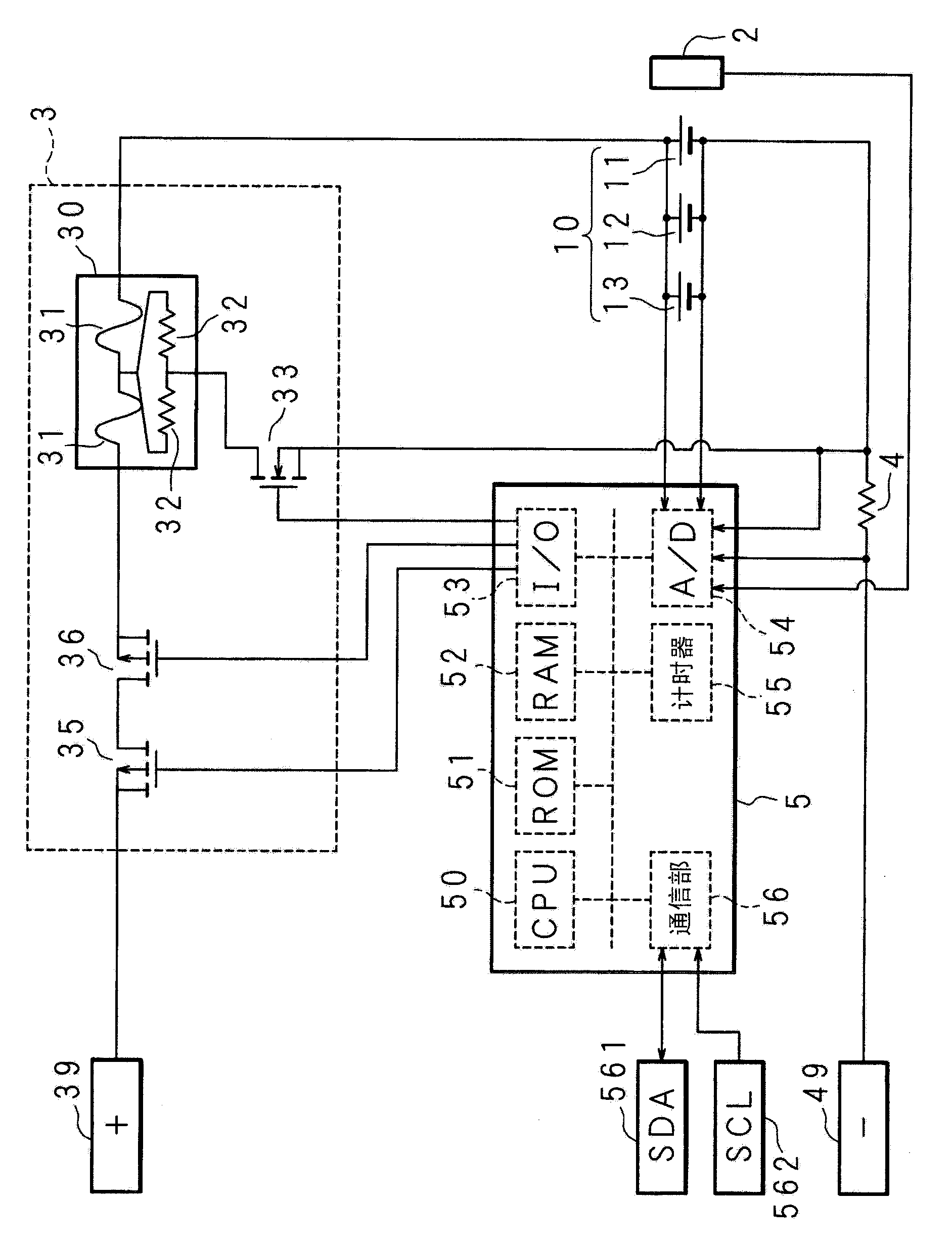
[0045] figure 1 It is a block diagram showing a configuration example of the assembled battery according to the present invention. In the figure, 10 is a battery block, and the battery block 10 is formed by connecting secondary batteries 11, 12, and 13 composed of lithium ion batteries in parallel with a conductive connector not shown. In the vicinity of the battery block 10, a temperature sensor 2 for detecting the temperature of the battery block 10 is arranged. The secondary batteries 11, 12, and 13 may be other batteries such as nickel-hydrogen batteries and nickel-cadmium batteries. In addition, the number of secondary batteries constituting the battery block 10 is not limited to three, and may be two or four or more.

[0046] The positive terminals of the secondary batteries 11, 12, and 13 are connected to the positive (+) terminal 39 via a cutoff portion 3 for cutting off the charge and discharge current of the secondary batteries 11, 12, and 13. The negative terminals o...

Embodiment approach 2

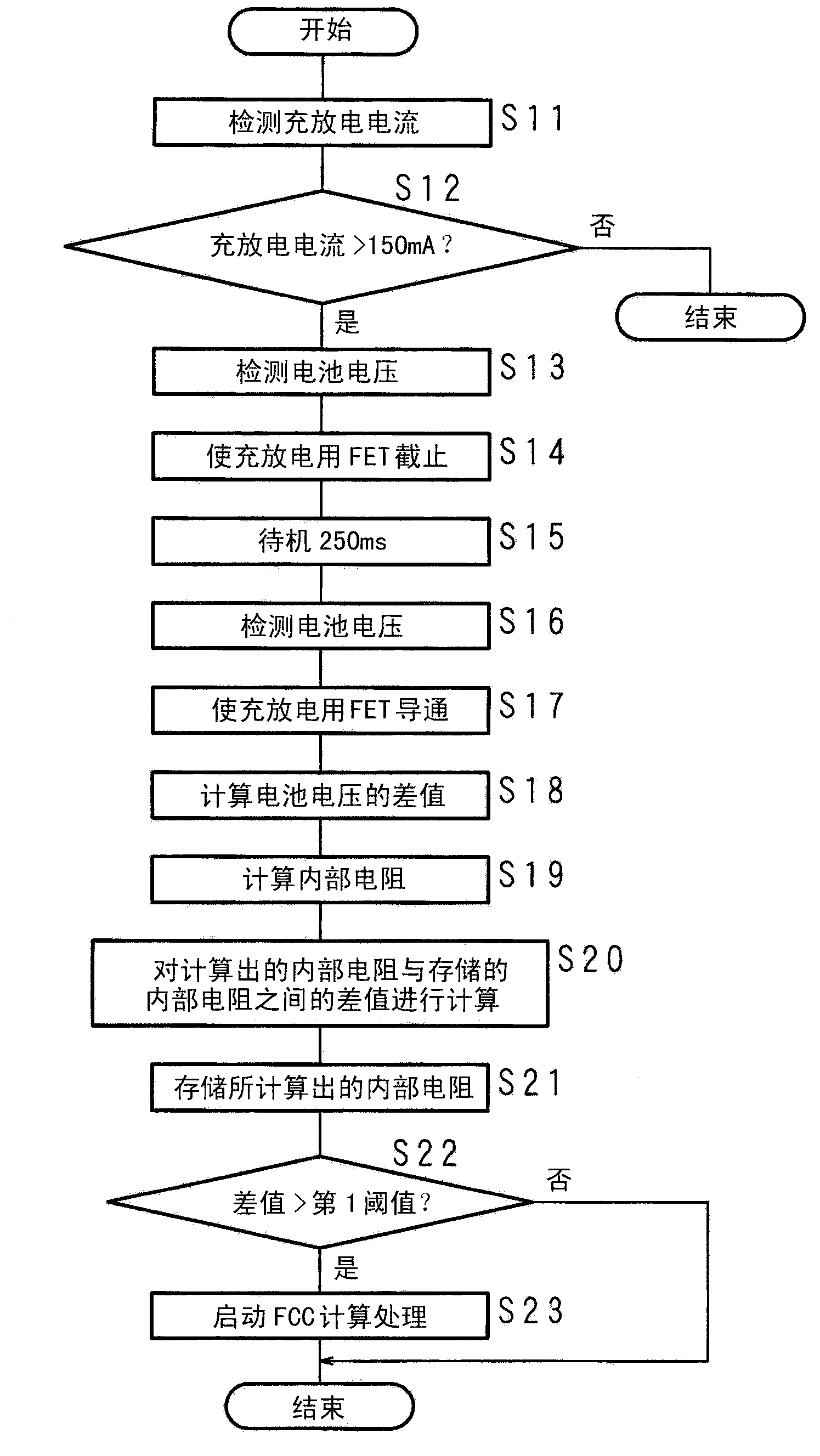
[0088] In the first embodiment, an abnormality related to the parallel capacity of the secondary batteries 11, 12, and 13 is determined. In contrast, in the second embodiment, an abnormality related to the battery voltage of the secondary batteries 11, 12, and 13 is determined.

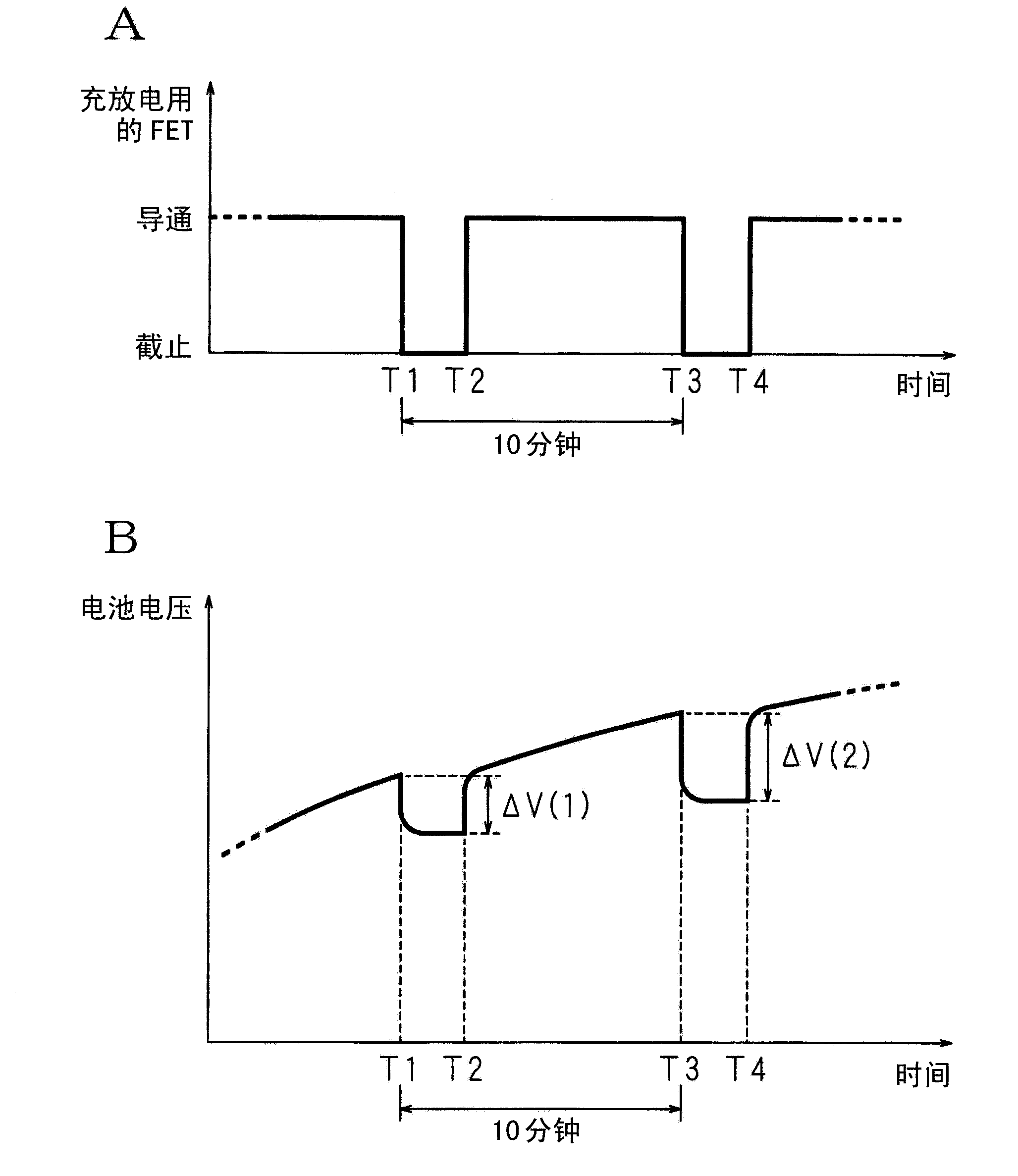
[0089] For example, in the secondary batteries 11, 12, and 13, signs of a local short circuit between the electrodes (positive and negative electrodes) are found in the interior of the secondary battery 13, but even if it is left alone, the electrodes may The short-circuit between time develops and causes accidents such as fire and rupture of the assembled battery.

[0090] Therefore, in the second embodiment, for the battery voltages of the secondary batteries 11, 12, and 13 detected in time series during the period when neither charging nor discharging is performed, the newly detected battery voltage is compared with the previous detected battery voltage. When the battery voltage is lower than the voltag...


PUM


Abstract

The present invention provides an abnormity determining method for a battery pack and the battery pack thereof. Whether the secondary battery is abnormal can be reliably determined in the battery which is obtained through connecting a plurality of secondary batteries. In charging of the secondary batteries, after stopping EFT which is inserted into a charging/discharging path for charging/discharging for 250ms (between time T1 and time T2 and between time T3 and time T4) is repeated every 10 minutes, the secondary battery is conducted. Based on differences (deltaV(1) and deltaV(2)) of the secondary batteries before conduction and after conduction and charging current detected before conduction, the internal resistance of the secondary battery is calculated every 10 minutes and is stored in a RAM. Hereon, on condition that the difference between a newly calculated internal resistance and the internal resistance which is formerly calculated and stored in the RAM is larger than a first threshold value, whether the secondary battery is abnormal is determined through comparing a difference between the newly calculated FCC (full capacitance) and the FCC that is formerly calculated and stored in the RAM with a second threshold.

Description

Technical field [0001] The present invention relates to an abnormality determination method for an assembled battery for determining whether the secondary battery is abnormal in an assembled battery including a plurality of secondary batteries connected in parallel, and an assembled battery for executing the abnormality determination method. Background technique [0002] Regarding secondary batteries, in most cases, multiple secondary batteries (batteries) of standard capacity are combined and used as a battery pack (battery pack). For example, connecting multiple batteries in series or parallel can increase the terminal voltage and battery capacity, or connecting multiple batteries in series and parallel can increase both the terminal voltage and battery capacity. In a battery pack connected by combining multiple batteries in this way, if the charging voltage applied to each battery and the value of the charge and discharge current flowing in each battery are unbalanced and the ...

Claims


Application Information

Patent Timeline
IPC IPC(8): G01R31/36H02J7/00H01M10/42
CPCY02E60/12Y02E60/10
Inventor 冈让治川角笃史
Owner SANYO ELECTRIC CO LTD
Why Eureka
Try Eureka