Light-emitting diode (LED) backlight drive circuit and liquid crystal displayer (LCD)

A backlight drive circuit, liquid crystal display technology, applied in static indicators, instruments, optics, etc., can solve problems such as hidden dangers, temperature rise, inconvenient adjustment, etc., and achieve the effect of reducing hidden dangers and improving safety performance.

Inactive Publication Date: 2013-05-08
TCL CHINA STAR OPTOELECTRONICS TECH CO LTD
View PDF3 Cites 6 Cited by
  • Summary
  • Abstract
  • Description
  • Claims
  • Application Information

AI Technical Summary

Problems solved by technology

[0004] 1. The single frequency setting resistor R has only some commonly used resistance values. When it is necessary to adjust the driving frequency of the MOS tube, it may be difficult to find a resistor with a suitable resistance value, which is inconvenient to adjust;
[0005] 2. When testing the electrical characteristics of the circuit board, it is necessary to test the safety of each component in the open circuit (open) / short circuit (short) state. When the frequency setting resistor R is short-circuited, according to the formula: f (KHz) = constant / R, the frequency of the MOS tube drive signal tends to infinity, the switching loss on the MOS tube will be very large, the temperature will rise sharply, and there may be a safety hazard that the MOS tube will explode

Method used


Image

  • Light-emitting diode (LED) backlight drive circuit and liquid crystal displayer (LCD)
  • Light-emitting diode (LED) backlight drive circuit and liquid crystal displayer (LCD)

Examples


Embodiment Construction

[0017] Preferred embodiments of the present invention will be described below with reference to the accompanying drawings.

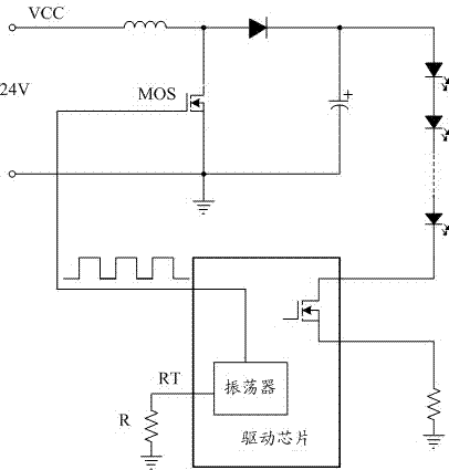
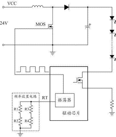
[0018] An LED backlight driving circuit provided in Embodiment 1 of the present invention includes: a driving chip and a frequency setting circuit, the frequency setting circuit includes at least two groups of resistors connected in parallel, one end is connected to the frequency setting pin RT of the driving chip, and the other end is grounded. It is used to adjust the frequency of the MOS tube driving signal by changing the resistance value of at least one of these resistors.

[0019] For details, please refer to figure 2 As shown, the frequency setting circuit includes two sets of resistors connected in parallel, wherein the first set of resistors includes R1 and R2, and R1 and R2 are connected in series; the second set of resistors includes R3 and R4, and R3 and R4 are connected in series. Under this circuit structure, the reciprocal of the equival...


PUM


Abstract

The invention provides a light-emitting diode (LED) backlight drive circuit which comprises a drive chip and a frequency setting circuit. The frequency setting circuit comprises at least two groups of resistors in parallel connection, one ends of the resistors are connected with a frequency setting lead foot RT of the drive chip, the other ends of the resistors are grounded, and the arrangement is used for changing at least one resistance value of the resistors so as to adjust the frequency of a drive signal of a metal oxide semiconductor (MOS) tube. The invention further provides a liquid crystal displayer (LCD). According to the LED backlight drive circuit and the LCD, due to the fact that a plurality of the resistors in serial and parallel connection are adopted, more accurate resistance values can be obtained, and the frequency of the drive signal of the MOS tube is convenient to accurately adjust; and when any of the resistors is in an open circuit or short circuit situation, the presence of the other resistors can also guarantee that the abnormal situation of infinitesimal or infinitely-great frequency of the drive signal of the MOS tube is not prone to occurring, the potential safety hazards after open circuit or short circuit happens to any resistor are reduced, and the safety performance is promoted.

Description

technical field [0001] The invention relates to the field of image display, in particular to an LED backlight driving circuit and a liquid crystal display. Background technique [0002] In the LED backlight drive circuit, the drive signal of the MOS tube (Metal-Oxide-Semiconductor Field Effect Transistor, Metal-Oxide-Semiconductor Field Effect Transistor) is given by the constant current drive chip, and the frequency of the drive signal is given by the RT pin (frequency setting pin) The external resistance value is determined by the calculation formula: f (KHz)=constant / R, that is, the frequency f is equal to a constant (this constant value is determined by each driver chip manufacturer, and the constant value of different manufacturers’ driver chips is different) and the resistance Ratio of R values. [0003] In the LED backlight drive circuit, the frequency of the MOS tube driving signal is generally selected at 100~200KHz. When the frequency is too small, the conduction ...

Claims


Application Information

Patent Timeline
Patent Type & Authority Applications(China)
IPC IPC(8): G09G3/34G09G3/36H05B44/00
CPCG09G3/34G09G3/3406G02F1/133612H05B45/3725G02F1/1336
Inventor 张华
Owner TCL CHINA STAR OPTOELECTRONICS TECH CO LTD
Why Eureka
Try Eureka