Control method of high precision single phase digital phase-locked loop based on static reactive generator

A digital phase-locked loop, static reactive power technology, applied in reactive power compensation, reactive power adjustment/elimination/compensation and other directions, can solve problems such as low engineering feasibility, achieve simple implementation, intuitive compensation principle, and simple detection process Effect

Inactive Publication Date: 2013-05-08
SHANDONG JINHUA ELECTRIC POWER
View PDF1 Cites 6 Cited by
  • Summary
  • Abstract
  • Description
  • Claims
  • Application Information

AI Technical Summary

Problems solved by technology

In the current algorithm research, most of them use the theory of instantaneous reactive power or other detection methods for corresponding control. These methods require a large number of mathematical operations, which have a certain impact on the real-time performance of the system, and their engineering feasibility is small.

Method used


Image

  • Control method of high precision single phase digital phase-locked loop based on static reactive generator
  • Control method of high precision single phase digital phase-locked loop based on static reactive generator
  • Control method of high precision single phase digital phase-locked loop based on static reactive generator

Examples


Embodiment Construction

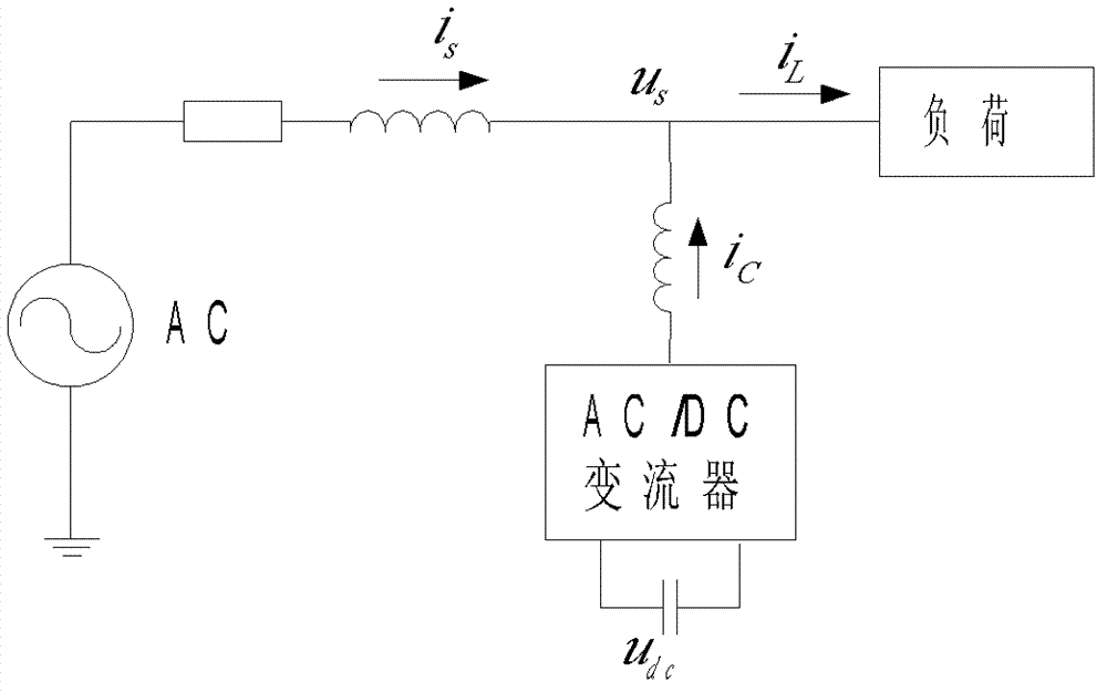
[0024] The single-phase structure diagram of the system is attached figure 1 shown. attached figure 1 The fundamental reactive power of the system shown in is very large, and the power factor is low. i s is the supply current, i L is the load current, i c is the compensation current, U c is the DC side capacitor voltage of the converter, U s is the power supply voltage, and the grid voltage is assumed to be an undistorted sine wave, directly expressed as U s The phase of is the reference phase, and the compensation current i output on the AC side inductance L of the converter c Including fundamental active current, fundamental reactive current and harmonic current.

[0025] Let the grid voltage be an undistorted sine wave, u s (t)=U sM sin(ωt), the instantaneous load current is as follows:

[0026] i L (t)=I L sin(ωt+θ)=I p sin(ωt)+I q cos(ωt) (1)

[0027] The control goal of the algorithm is to make the current sent by the compensation device the reactive curr...


PUM


Abstract

The invention relates to a control method of a reactive compensation device. The high precision single phase digital phase-locked loop based on a static reactive generator comprises the following steps: 1,load current momentary value is detected, a network voltage is an orthoscopic sine wave; 2,period average value is conducted on a direct current lateral capacitance voltage universal decimal classification (Udc), amplitude value of an active current is achieved through a digital phase-locked loop; 3,the load current achieved by sampling and the cosine of theta are multiplied and averaged in a period to extract a fundamental wave reactive current component; 4,the active current, the reactive current and a supply current are added to achieve a target current; 5,a pulse width modulation (PWM) convertor is controlled in a hysteresis comparison mode after an actual output current and the target current are compared. The control method of the high precision single phase digital phase-locked loop based on the static reactive generator has the advantages that complicated process of detecting the active current component and the reactive current component is avoided, process of detecting a harmonic wave is simplified, reactive compensation range is wide, and stability performance is good.

Description

technical field [0001] The invention relates to a control method of a reactive power compensation device, in particular to a control method using a phase-locked loop. Background technique [0002] With the development of power electronics technology, the use of various nonlinear and impact equipment has brought a lot of harmonic pollution to the power grid, resulting in problems such as low power factor, serious harmonic pollution, and increased system loss. In recent years, various FACTS devices for reactive power compensation and harmonic control have been proposed one after another. [0003] The compensation performance of static var generator depends on its harmonic and reactive current detection method and compensation current control method. At present, the detection method of reactive harmonic current and the compensation current control algorithm are developing rapidly. In the current algorithm research, most of them use the theory of instantaneous reactive power o...

Claims


Application Information

Patent Timeline
Patent Type & Authority Applications(China)
IPC IPC(8): H02J3/18
CPCY02E40/30
Inventor 解大宋元锋张延迟贾玉健张玉涛周长金庄骏鹏何伟刘林泉王雷荆茂来
Owner SHANDONG JINHUA ELECTRIC POWER
Why Eureka
Try Eureka