Farad capacitor charger

A technology of Farad capacitors and chargers, applied in current collectors, battery circuit devices, electric vehicles, etc., can solve problems such as charger damage, and achieve the effects of preventing overcharging, saving energy, and protecting Farad capacitors.

Active Publication Date: 2013-05-08
ZONECHARGE (SHENZHEN) WIRELESS POWER TECH CO LTD
View PDF4 Cites 1 Cited by
  • Summary
  • Abstract
  • Description
  • Claims
  • Application Information

AI Technical Summary

Problems solved by technology

[0004] In view of the ultra-low resistance of the farad capacitor, if the traditional wired charging method is used to charge the farad capacitor, the farad capacitor will be short-circuited at the moment when the power is turned on, which will easily lead to damage to the charger.

Method used


Image

  • Farad capacitor charger
  • Farad capacitor charger
  • Farad capacitor charger

Examples


example 1

[0022] Example 1. The working principle of the farad capacitor charger

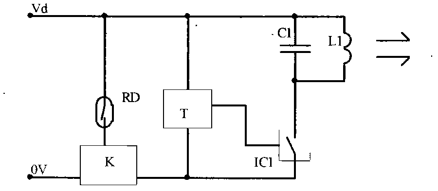
[0023] in the attached figure 1 Among them, the farad capacitor charger, which includes the following structure: a L1C1 resonant transmitting circuit, a transmitting driver IC1, a timer T, a reed switch RD and a group of electronic switches K; the resonant transmitting circuit L1C1 is controlled by the transmitting driver IC1, the transmitting driver IC1 is controlled by the timer T, and the timer T is controlled by the magnetic switch. The specific structure and working principle are as follows:

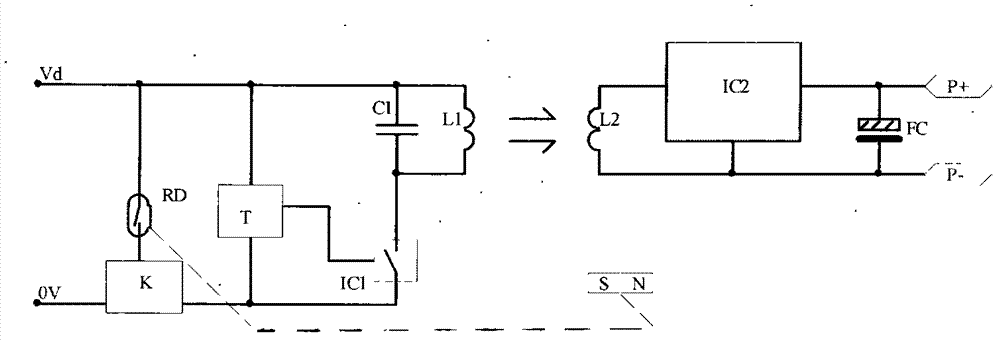
[0024] in the attached figure 1 And attached figure 2 Among them, the L1C1 resonant transmitting circuit is a parallel resonant transmitting circuit. One end of this circuit is connected to the positive pole Vd of the power supply, and the other end is connected to the output terminal of the transmitting driver IC1. The power supply terminal of the transmitting driver IC1 is connected to the output terminal ...

example 2

[0029] Example 2. Another principle of Farad capacitor charger

[0030] There are other options for implementing the Farad capacitor charger of Example 1:

[0031] Solution 1: Use a single-chip MCU to write the timing program and the oscillation and driver required for the launch, and add a power output tube outside the MCU to replace the timer T and launch driver IC1 in Example 1.

[0032] Solution 2: Use Hall (Hall) sensor instead of reed switch RD to realize the magnetic control function.

example 3

[0033] Example 3. Structural layout of Farad capacitor charger

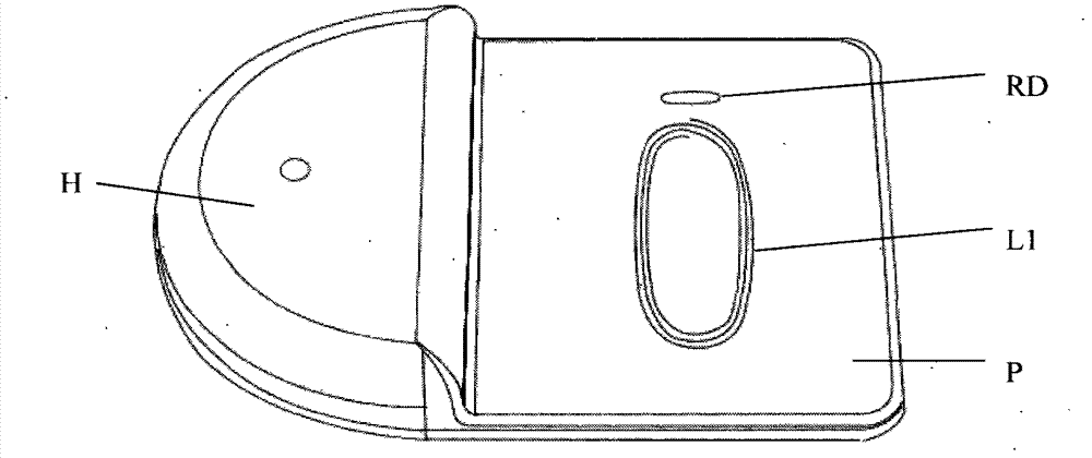
[0034] like image 3 , the plastic shell P is divided into upper and lower shells, and the cavity H is used to place a PCB. The components on the PCB include: electronic switch K, timer T, resonant capacitor C1 and transmitting driver IC1, etc., transmitting coil L1 and dry reed Tube RD is placed on the other side of the cavity;

[0035] The position requirements of the transmitting coil L1 and the reed switch RD: the position of the transmitting coil L1 is aligned with the receiving coil L2 up and down, and the position of the reed switch RD is aligned with the magnet SN up and down, so as to ensure that the reed switch RD is connected when the magnet SN is close. At the same time, when the transmitting circuit is working, the receiving coil L2 can well receive the energy from the transmitting coil L1.


PUM


Abstract

The invention discloses a farad capacitor charger which is a wireless charger aiming at charging a farad capacitor, and the farad capacitor charger can convert electric energy to magnetic energy to send out. The farad capacitor comprises a launch control (LC) resonance emitting return circuit, an emitting actuator, a timer, a reed switch and a group of electronic switches. The resonance emitting return circuit is controlled by the emitting actuator which is controlled by the timer, and the timer is controlled by the electric switches which are controlled by the reed switch. The LC resonance emitting return circuit is a parallel connection type resonance emitting circuit, one end of the LC resonance emitting return circuit is connected with a positive pole of a power source, and the other end of the LC resonance emitting return circuit is connected with an output end of the emitting actuator. The power source end of the emitting actuator is connected with an output end of the timer, and the ground end of the emitting actuator is connected with a negative pole of the timer. The power source end of the timer is connected with the positive pole of the power source, the electronic switches are connected between the negative pole of the power source and the negative pole of the timer in series, and the reed switch is connected on the positive pole of the power source and at the control ends of the electronic switches.

Description

technical field [0001] The invention relates to a wireless charger, which is a wireless charger for charging farad capacitors. Background technique [0002] Farad capacitors are also called super capacitors. Compared with batteries, they have the following characteristics: [0003] The charging speed is fast, charging for 10 seconds to 10 minutes can reach more than 95% of its rated capacity; ultra-low series resistance, power density is more than ten times that of lithium-ion batteries, suitable for high-current discharge; super long life, charge and discharge greater than 50 10,000 times, about 500 times that of Li-Ion batteries, and about 1,000 times that of Ni-MH and Ni-Cd batteries; it can be charged with a large current, the charging and discharging time is short, the requirements for the charging circuit are simple, and there is no memory effect; maintenance-free, It can be sealed; there is no pollution in the raw material composition, production, use, storage and di...

Claims


Application Information

Patent Timeline
Patent Type & Authority Applications(China)
IPC IPC(8): H02J7/00H02J17/00H02J7/34H02J50/00
Inventor 朱斯忠
Owner ZONECHARGE (SHENZHEN) WIRELESS POWER TECH CO LTD
Why Eureka
Try Eureka