
Multifunctional feeding device for extruder

A feeding device and multi-functional technology, applied in the field of feeding devices and multi-functional feeding devices for extruders, can solve the problems of inapplicability, inconvenient material addition, high labor intensity, etc., and achieve the effect of simple structure and complete functions

Inactive Publication Date: 2013-05-15
SHENYANG CHUANGDA TECH TRADE MARKET
View PDF0 Cites 3 Cited by
  • Summary
  • Abstract
  • Description
  • Claims
  • Application Information

AI Technical Summary

Problems solved by technology

There are currently four commonly used feeding methods, one is blast feeding, which uses wind to blow raw materials into the feeding pipe, and then enters the hopper through the cyclone separator. This feeding method is only suitable for conveying granular materials, while It is not suitable for conveying powder; the second type is screw forced feeding, which uses the rotating spiral to make the raw material pass through the feeding port evenly, so as to avoid the "bridging" phenomenon at the feeding port. On the machine, it takes up a lot of upper space, and it is inconvenient to add materials; the third is spring feeding, which is driven by the motor to rotate the spring at high speed, and the material is driven by the spring to move up the hose, and when it reaches the feeding port, it is under the centrifugal force. The disadvantage of this method is that the spring is easily damaged, the hose is easy to wear, and the exposed part of the spring is easy to burn out the motor; the fourth is manual feeding, so that workers The labor intensity is very high, and the place where the dust density is the highest at the feeding port, long-term inhalation is harmful to the body

Method used


Image

  • Multifunctional feeding device for extruder

Examples


Embodiment Construction

[0012] The present invention will be described in detail below in conjunction with the accompanying drawings and embodiments.

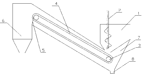
[0013] Such as figure 1 The multifunctional feeding device for the extruder shown includes a storage bin 1, a conveyor belt 4, and a hopper 6. A screw 2 is arranged inside the storage bin 1, and the screw rod 2 is at the outlet of the storage bin 1. Directly above, the conveyor belt 4 is supported by two pulleys 3, one end of which is arranged below the outlet of the storage bin 1, and the other end is arranged obliquely above the hopper 6, and a bulk material belt 7 is arranged around the conveyor belt 4 , used to receive the materials scattered outside during the conveying process, and a discharge port 8 is set under the bulk material belt 7 .

[0014] The conveyor belt 4 is composed of two layers, the lower layer is made of ordinary conveyor belt material, and the upper layer is adhered with a layer of stainless steel.

[0015] The outer edge of ...


PUM


Abstract

The invention relates to a feeding device and especially relates to a multifunctional feeding device for an extruder and belongs to the technical field of plastic processing machinery auxiliary equipment. The multifunctional feeding device comprises a material storage bin, a material conveyer belt and a hopper. A screw rod is arranged in the material storage bin. The screw rod is located right above an outlet of the material storage bin. The material conveyer belt is supported by two belt wheels. One end of the material conveyer belt is located under the outlet of the material storage bin and the other end of the material conveyer belt is located obliquely above the hopper. The periphery of the material conveyer belt is provided with a spilled material belt for receiving spilled materials in conveying. The outlet is arranged below the spilled material belt. The multifunctional feeding device has a simple structure. Compacted materials in the material storage bin are loosed by the screw rod, then fall on the material conveyer belt, then are conveyed to the hopper by material conveyer belt circulating rotation, and then enter into the hopper under the action of a scraper blade. The multifunctional feeding device can be used for powder and for feeding granules and short threads, and has complete functions.

Description

technical field [0001] The invention relates to a feeding device, in particular to a multifunctional feeding device for an extruder, and belongs to the technical field of auxiliary equipment for plastic processing machinery. Background technique [0002] The feeding device is an important mechanism to ensure that the material is continuously and evenly supplied to the extruder to achieve continuous extrusion. The correct design and selection of the feeding device is directly related to the output and quality of the extruder, the labor intensity of the workers, and whether the continuous production and automation can be realized. There are currently four commonly used feeding methods, one is blast feeding, which uses wind to blow raw materials into the feeding pipe, and then enters the hopper through the cyclone separator. This feeding method is only suitable for conveying granular materials, while It is not suitable for conveying powder; the second type is screw forced feed...

Claims


Application Information

Patent Timeline
IPC IPC(8): B29C47/10
Inventor 贵阳刘昊湦
Owner SHENYANG CHUANGDA TECH TRADE MARKET
Learn More