Double-pressurizing-channel packer applied to oil tube sealing and detection

A technology of sealing detection and double pressurization, which is applied in the directions of sealing/isolation, wellbore/well components, earthwork drilling and production, etc. It can solve the problem that the setting pressure of the packer cannot be adjusted, the sealing performance of the rubber cylinder cannot be guaranteed, and the sealing The problem of large volume of the inner cavity of the device can be solved, so as to reduce the operation risk, save the detection time, and shorten the setting time

Active Publication Date: 2013-05-15
BC P INC CHINA NAT PETROLEUM CORP +1
View PDF5 Cites 2 Cited by
  • Summary
  • Abstract
  • Description
  • Claims
  • Application Information

AI Technical Summary

Problems solved by technology

This kind of packer has disadvantages: 1. The inner chamber of this kind of packer has a large volume and high gas consumption, which greatly increases the operating cost; It takes a long time; 3. The setting pressure of the packer cannot be adjusted, and the sealing performance of the rubber cartridge cannot be guaranteed; 4. When unsealing, it is easy to cause the packer to jump due to the early closure of the pressure relief channel, which increases the operation risk

Method used


Image

  • Double-pressurizing-channel packer applied to oil tube sealing and detection
  • Double-pressurizing-channel packer applied to oil tube sealing and detection

Examples


Embodiment 1

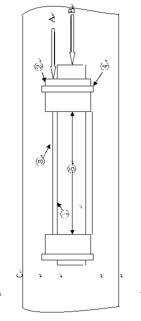
[0026] As a preferred embodiment of the present invention, the present invention is mainly composed of a mandrel 1, a liquid cylinder 2, an outer cylinder 3, a well gauge 4, and a rubber cartridge. Inject hydraulic oil, push the piston to move down along the mandrel 1 and squeeze the rubber tube together with the well gauge 4, and expand it to realize setting. After setting, pump high-pressure mixed gas into the packer through channel B, and the high-pressure The mixed gas continues to pressurize to the detection pressure value in the trap space between the rubber cylinder and the inner wall C of the oil pipe through the pressure transmission hole on the outer cylinder 3 . After the test is finished, the test gas in the trapped space is released first, and then the setting pressure is released, the liquid cylinder 2 is reset, the rubber tube shrinks, and then the seal is unsealed. In the design of the invention, different pressurization channels are used for setting and detect...

Embodiment 2

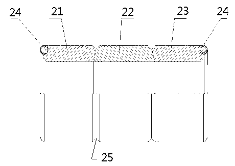
[0028] As the best embodiment of the present invention, the rubber cartridge includes a rubber cartridge body, the rubber cartridge body includes a head end rubber cartridge body 21, a middle rubber cartridge body 22 and an end rubber cartridge body 23, the head end rubber cartridge body 21, The middle rubber cartridge body 22 and the end rubber cartridge body 23 have an integrated structure, and the hardness of the head rubber cartridge body 21 and the end rubber cartridge body 23 is higher than that of the middle rubber cartridge body 22 . The rubber cartridge body is a three-stage structure, including the head rubber cartridge body 21, the end rubber cartridge body 23 and a middle rubber cartridge body, and the head end rubber cartridge body 21 and the end rubber cartridge body 23 are connected with the middle rubber cartridge body. A deformation space 25 is provided at the junction. A metal support member 24 is disposed in the head rubber cartridge body 21 and the end rubb...


PUM


Abstract

The invention discloses a double-pressurizing-channel packer applied to oil tube sealing and detection. The double-pressurizing-channel packer applied to oil tube sealing and detection comprises a mandrel, a hydraulic cylinder, an outer cylinder, a gauge cutter and rubber sleeves. The outer cylinder is sleeved on the mandrel. The rubber sleeves are respectively arranged at two ends of the outer cylinder and connected with the gauge cutter. The hydraulic cylinder is arranged at one side outside the gauge cutter. A hydraulic oil channel and a high-pressure commingler channel are arranged on the hydraulic cylinder. According to the double-pressurizing-channel packer applied to oil tube sealing and detection, due to the facts that the double-pressurizing-channel packer is small in an inner cavity and low in gas consumption, operation cost is reduced, setting time is short and detection time is saved.

Description

[0001] technical field [0002] The invention relates to the technical field of oil testing and testing the safety of downhole pipe strings, in particular to a packer suitable for oil pipe sealing detection. Background technique [0003] In the development of domestic high-temperature, high-pressure sour gas fields, the tubing in the well is generally required to be used for more than 10 years after it is put into production. The connection quality can meet the production requirements. [0004] The Chinese patent document with the publication number CN202531094U and the publication date of November 14, 2012 discloses a compression packer, which is to solve the problem of short validity period of conventional packers, high risk of later operation, and poor adaptability to oil pressure. It is designed for problems such as the difficulty of opening and closing the well flushing channel, mainly including the upper and lower joints connected to the center pipe, the liner fitted ...

Claims


Application Information

Patent Timeline
Patent Type & Authority Applications(China)
IPC IPC(8): E21B33/128
Inventor 潘登庞东晓许峰舒梅陈华良项培军贺秋云杨光炼
Owner BC P INC CHINA NAT PETROLEUM CORP
Why Eureka
Try Eureka