Mushroom-like groove bi-direction rotating fluid dynamic pressure type machine sealing structure

A mechanical seal, fluid dynamic pressure technology, applied in the direction of engine seals, mechanical equipment, engine components, etc., can solve the problems of small leakage, wear resistance, poor wear resistance, end surface temperature rise, etc.

Active Publication Date: 2013-05-15
ZHEJIANG UNIV OF TECH
View PDF6 Cites 14 Cited by
  • Summary
  • Abstract
  • Description
  • Claims
  • Application Information

AI Technical Summary

Problems solved by technology

[0003] The invention overcomes the disadvantages of non-contact mechanical seals such as large leakage under high parameter conditions, poor lubrication effect and wear resistance between sealing end faces, and rising end face temp

Method used


Image

  • Mushroom-like groove bi-direction rotating fluid dynamic pressure type machine sealing structure
  • Mushroom-like groove bi-direction rotating fluid dynamic pressure type machine sealing structure
  • Mushroom-like groove bi-direction rotating fluid dynamic pressure type machine sealing structure

Examples


Embodiment 1

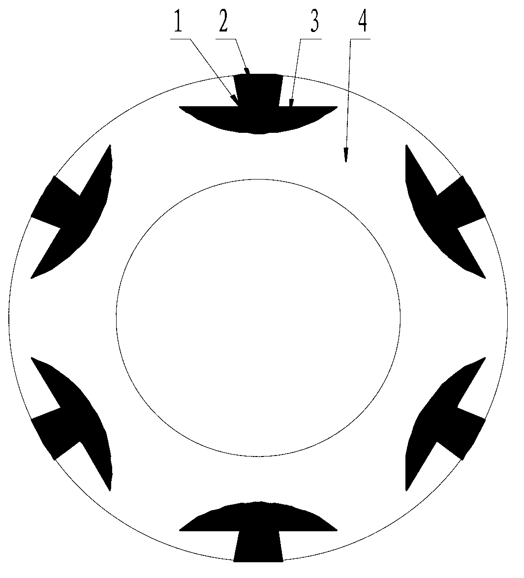
[0030] refer to figure 1 , figure 2 , Like a mushroom-shaped groove two-way rotating hydrodynamic mechanical seal structure, it includes a dynamic ring and a static ring of the mechanical seal. The sealing end surface of at least one sealing ring in the moving ring or the static ring has a plurality of mushroom-like grooves 1 uniformly distributed in the circumferential direction for liquid sealing. The characteristics of the mushroom-like groove 1 are drainage grooves 2 and return grooves. 3 consists of two parts. The drainage groove 2 extends radially, and the width gradually narrows along the radial direction of the end surface from the upstream, that is, the high pressure side, to the downstream, that is, the low pressure side; The shape is a circular arc or an elliptical arc or a curved arc or a straight line. The end of the drainage groove 2 is connected to the return groove 3, and the ungrooved area between the mushroom-shaped grooves is a sealing dam 4.

[0031] T...

Embodiment 2

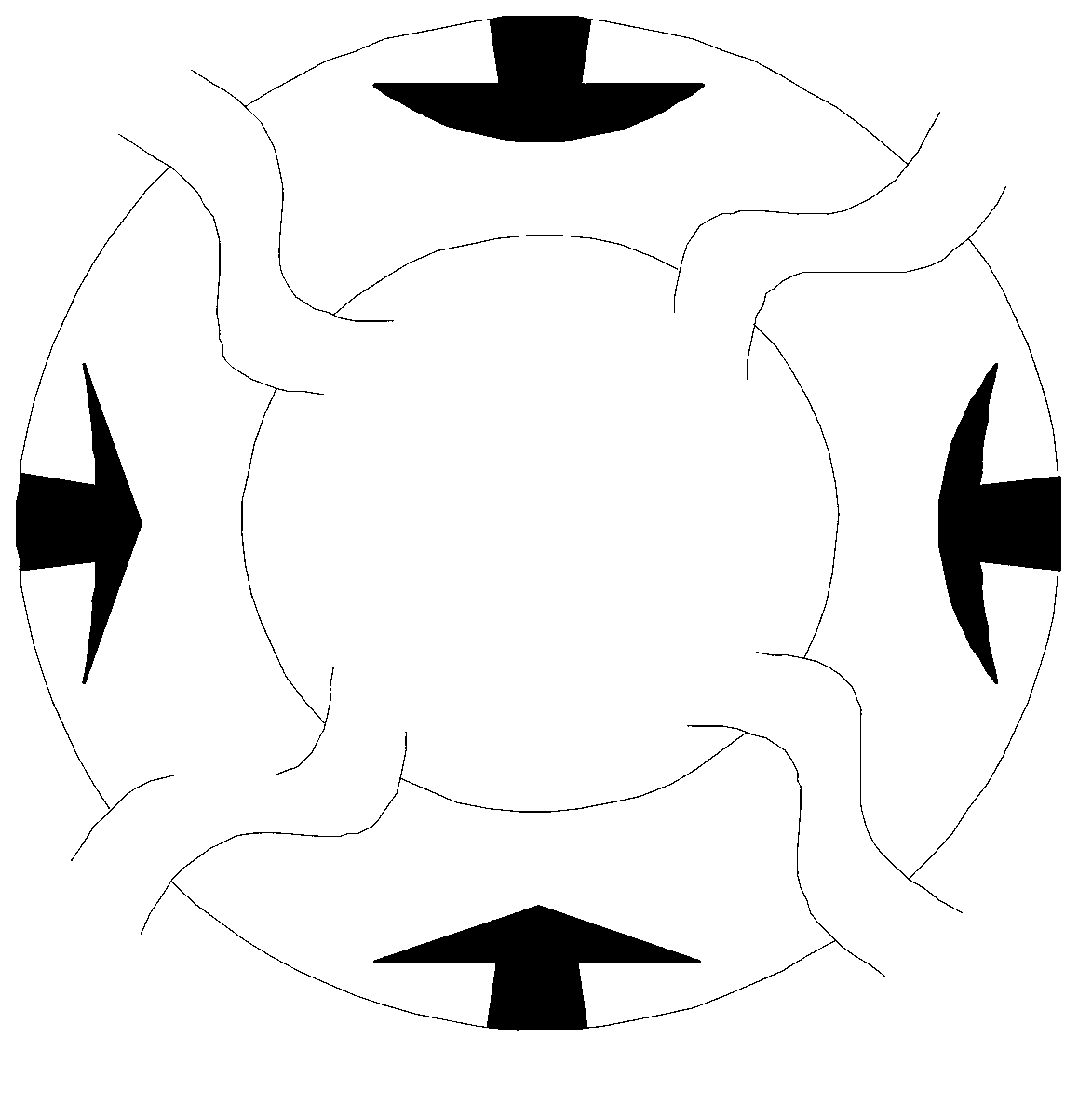
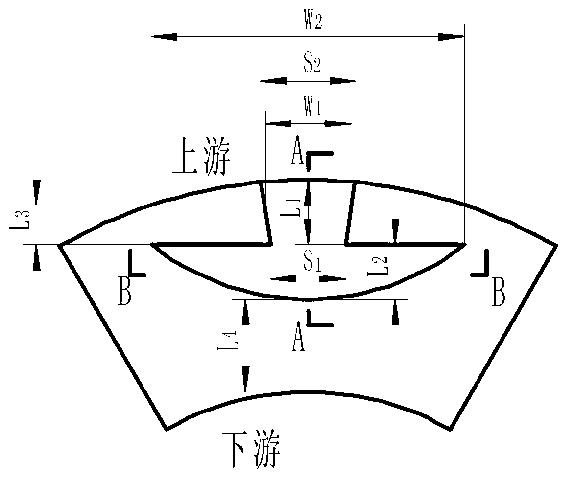
[0034] refer to image 3 , Figure 4 , Figure 5 , Image 6 , Figure 7 The difference between this example and Example 1 is that the drainage groove 2 becomes deeper in the radial direction, and the depth gradually becomes shallower along the radial direction of the end surface from upstream to downstream. Base bottom surface depth h of drainage groove 2 1 : 1μm≤h 1 ≤10μm; variable depth step height h 2 : 1μm≤h 2 ≤10μm; variable depth steps n 0 : 0≤n 0 ≤10; the aspect ratio of the deepening step of the drainage groove 2 γ 1 : 1≤γ 1 ≤5; the radial length L of the drainage groove 2 1 and seal face width W 1 Ratio L 1 / W 1 : 1 / 5≤L 1 / W 1 ≤1 / 2.

[0035] The drainage groove 2 becomes deeper along the radial direction, and the depth arrangement is to converge and become deeper along the radial straight line. The depth of the bottom surface of the drainage groove 2 is h 3 : 1μm≤h 3 ≤10μm; the depth h of the opening of the drainage groove 2 at the high pressure sid...

Embodiment 3

[0041] refer to Figure 8 The difference between this embodiment and Embodiment 1 and Embodiment 2 is that a sealing weir is added in the middle of the adjacent mushroom-shaped groove, so that the mushroom-shaped groove is separated from the circumferential direction, and it is also applicable to bidirectional rotation. All the other structures and implementations are the same as in Example one and Example two.


PUM

PropertyMeasurementUnit
Depthaaaaaaaaaa
Depthaaaaaaaaaa
Depthaaaaaaaaaa

Abstract

A mushroom-like groove bi-direction rotating fluid dynamic pressure type machine sealing structure comprises two sealing rings of mechanical seal. The two sealing rings refer to a movable ring and a static ring. A plurality of mushroom-like grooves for sealing liquid are evenly distributed on the circumference of the sealing end face of at least one of the movable ring and the static ring. Each mushroom-like groove is composed of a drainage groove and a returning groove. Each drainage groove extends in the radial direction, and the width of each drainage groove gradually becomes narrower from an upper stream (a higher-pressure side) to a lower stream (a lower-pressure side) along the end face in the radial direction. Each returning groove extends in the circumference direction and the radial direction and is in the shape of an arc, an oval arc, a curved arc, or a straight line. The tail end of each drainage groove is connected with each returning groove. Areas which are not provided with grooves and are between the mushroom-like grooves are sealing weirs. A ring belt formed by an area which is not provided with grooves on the circumference of the end face is a sealing dam.

Description

Technical field: [0001] The invention relates to a shaft end end face sealing device of a rotating machine, which is suitable for the shaft end sealing device of rotating shafts of various compressors, pumps, stirring tanks and other rotating machines, and belongs to the technical field of mechanical end face sealing. Background technique: [0002] At present, the shaft seal of fluid machinery often adopts mechanical seal. When the contact mechanical seal is started, the lack of fluid lubrication between the end faces will cause the frictional heat to rise and be accompanied by wear, deformation and even thermal cracking, so the seal life is shorter. Although the non-contact seal can overcome the shortcoming of the contact seal, almost all non-contact mechanical seals will increase the leakage of the seal gap while reducing the wear of the end face. During operation, the end face groove generates fluid dynamic pressure to increase the opening force of the end face, and the ...

Claims


Application Information

Patent Timeline
IPC IPC(8): F16J15/16F16J15/40
Inventor 彭旭东佘宝瑛孟祥铠李纪云王玉明
Owner ZHEJIANG UNIV OF TECH
Why Eureka
Try Eureka