Anemometer detecting thermal time constant of sensor

A time constant, anemometer technique applied in the direction of measuring fluid velocity, instruments, measuring devices, etc. using thermal variables

Active Publication Date: 2013-05-15
ANALOG DEVICES INT UNLTD
View PDF6 Cites 7 Cited by
  • Summary
  • Abstract
  • Description
  • Claims
  • Application Information

AI Technical Summary

Problems solved by technology

Also, the transistor is insulated by its plastic encapsulation, making its base-emitter junction respond slower to changes in air velocity

Method used


Image

  • Anemometer detecting thermal time constant of sensor
  • Anemometer detecting thermal time constant of sensor
  • Anemometer detecting thermal time constant of sensor

Examples


Embodiment Construction

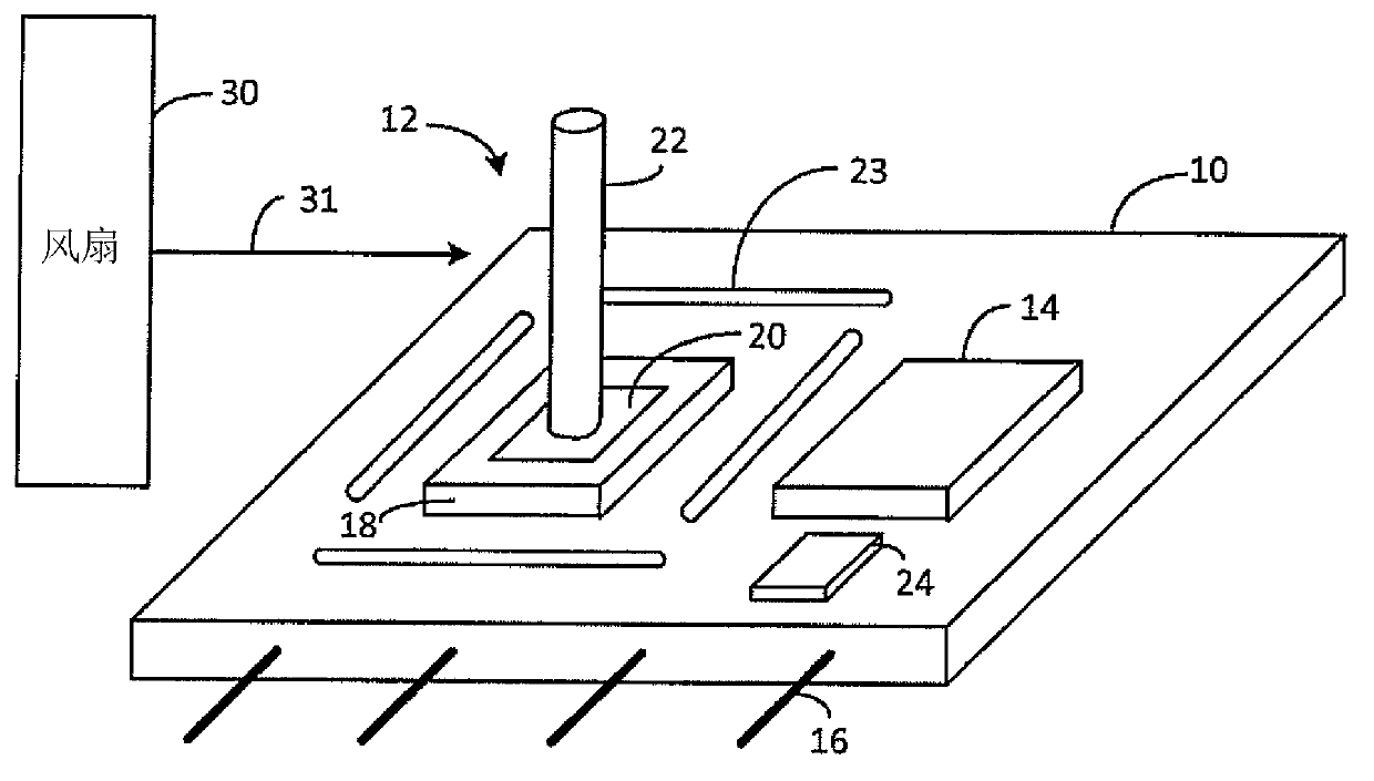
[0029] figure 1 A simplified printed circuit board (PCB) 10 on which an anemometer sensor 12 and a controller 14 are mounted is illustrated. In one embodiment, PCB 10 is only 3 x 3 cm or smaller. The PCB 10 can be conventional and is preferably thermally non-conductive. Circuits on PCB 10 are connected by copper traces. The power and I / O pins 16 of the PCB can be plugged into sockets on the motherboard or into cable connectors. In one embodiment, the air flow at various locations in the electrical equipment cabinet needs to be known, and the same PCB 10 may be located at various locations in the cabinet.

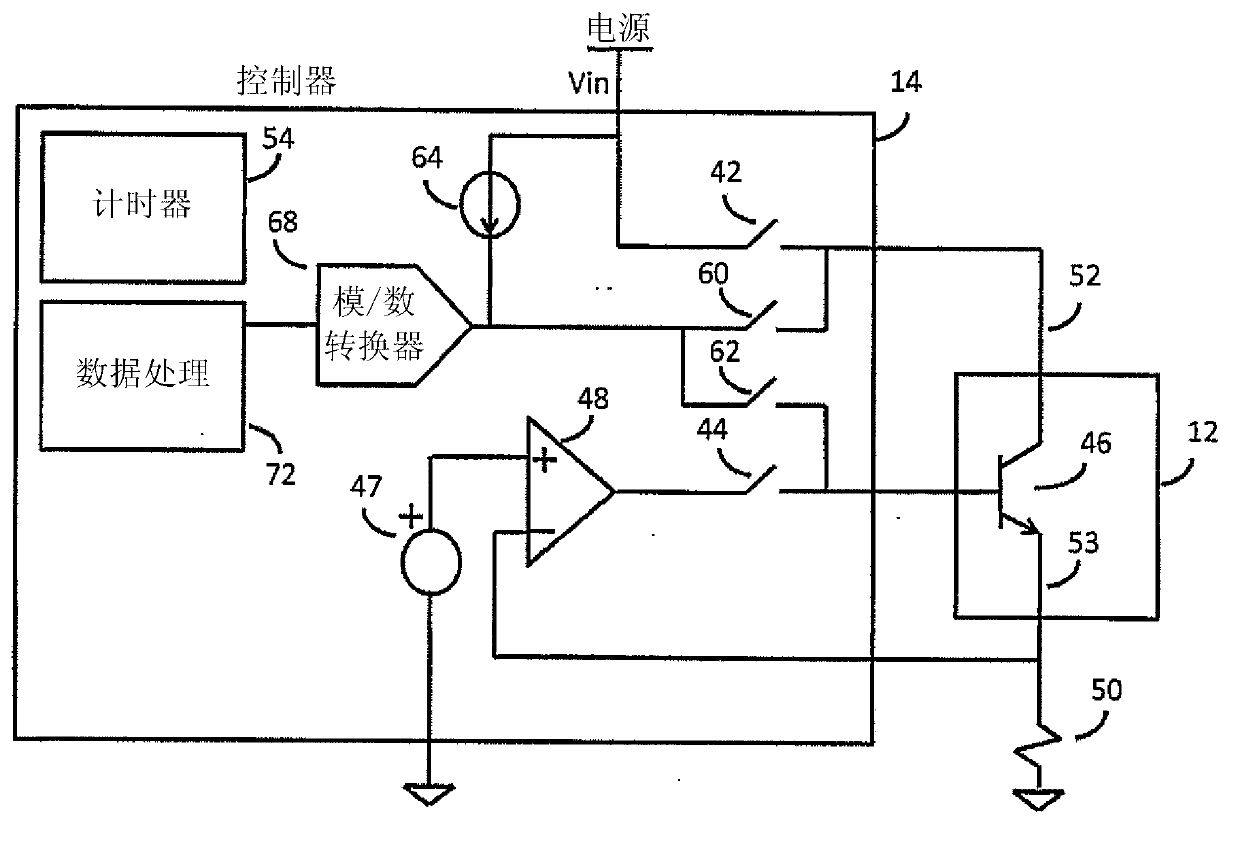
[0030] Bipolar transistors housed in package 18 are mounted on PCB 10 . The package may be a surface mount package with three or more terminals.

[0031] Package 18 has metal pads 20 to which the silicon die is thermally coupled. The metal pad 20 faces upwards. High thermal conductivity rods 22 are attached to thermal pad 20 and act as heat sinks. In one embodiment,...


PUM


Abstract

The invention provides an anemometer detecting thermal time constant of a sensor. In an anemometer for analyzing fluid a transistor sensor is heated by applying power to cause its base-emitter junction to rise from an ambient first temperature to a second temperature. The power is removed, and the Vbe is measured at intervals as the junction cools. The Vbe equates to a temperature of the junction. The temperature exponentially decreases, and the time constant of the decay corresponds to the fluid flow velocity. A best fit curve analysis is performed on the temperature decay curve, and the time constant of the exponential decay is derived by a data processor. A transfer function correlates the time constant to the fluid flow velocity. The transistor is thermally coupled to a metal rod heat sink extending from package, and the characteristics of the rod are controlled to adjust the performance of the anemometer.

Description

[0001] Cross References to Related Applications [0002] This application is based on, and claims priority to, U.S. Provisional Application No. 61 / 559,257, entitled "Anemometer," filed November 14, 2011 by the present inventor, which is assigned to the present assignee and Incorporated herein by reference. technical field [0003] The present invention relates to anemometers, and more particularly to solid state anemometers. Background technique [0004] Anemometers measure the flow of fluid, such as air passing over it. In electrical cabinets or boxes containing heat generating circuits, it is sometimes necessary to provide fan cooling. It is common practice to provide instrumentation in the cabinet to monitor temperature and air flow. The most common compact anemometers are hot wire and thermocouple. [0005] Hot wire types include wires with known resistance temperature characteristics. In one technique, the wire is heated by an electric current to achieve a target ...

Claims


Application Information

Patent Timeline
Patent Type & Authority Applications(China)
IPC IPC(8): G01P5/10
CPCG01F1/688G01F1/698G01F1/6986G01P5/10G01P1/00G01P5/02
Inventor 杰弗里·林恩·希思哈利·约瑟夫·克里伯格希思·狄克逊·斯图尔特
Owner ANALOG DEVICES INT UNLTD
Why Eureka
Try Eureka