Switch charging circuit and power management system

A charging circuit and charging voltage technology, which is applied to battery circuit devices, circuit devices, and energy-saving charging equipment, can solve the problems of complex implementation and chip heating, and achieve the effects of simple implementation, increased charging current, and clear structure

Active Publication Date: 2013-05-15
ALLWINNER TECH CO LTD
View PDF4 Cites 20 Cited by
  • Summary
  • Abstract
  • Description
  • Claims
  • Application Information

AI Technical Summary

Problems solved by technology

[0008] The purpose of the present invention is to provide a switch charging circuit and power management system, which solves the problems in the p...

Method used


Image

  • Switch charging circuit and power management system
  • Switch charging circuit and power management system
  • Switch charging circuit and power management system

Examples


Embodiment 1

[0042] For the convenience of description, the external power supply input terminal ACIN is marked as ACIN, the battery terminal BAT is marked as BAT, the system power supply terminal SYS is marked as SYS, and the reference power supply terminal REF is marked as REF. Correspondingly, the input power terminal voltage signal is marked as V ACIN , the battery terminal BAT voltage signal is marked as V BAT , the system power terminal SYS voltage signal is marked as V SYS , the reference power supply terminal REF voltage signal is marked as V REF .

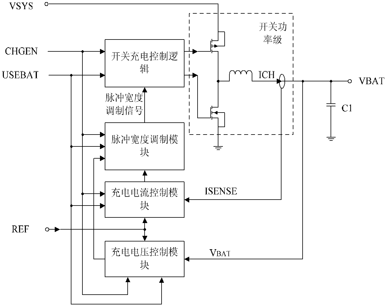
[0043] As a possible implementation, a switch charging circuit provided by the present invention includes a system power supply terminal SYS, a battery terminal BAT, a reference power supply terminal REF, a charging enable signal terminal, a battery power supply judgment signal terminal, and a switch charging module.

[0044] see figure 1 , the switch charging module includes a switch charging control logic module, a charging volta...

Embodiment 2

[0095] see Figure 8 , as a possible implementation, the power management system includes a first voltage comparison module, a second voltage comparison module, a logic control module, a first voltage maintenance module, a second voltage maintenance module, a first switch unit, a second switch The unit, a reference power supply terminal REF, an external power supply input terminal ACIN, a system power supply terminal SYS, a battery terminal BAT, and a switch charging module and a first voltage conversion module are also included.

[0096] The reference power terminal REF generates a reference voltage as a reference voltage for conversion and comparison by the power management system.

[0097] The first switch unit is connected to the external power input terminal ACIN, the first voltage maintaining module, the first voltage conversion module and the system power supply terminal SYS. A first switch tube is included, and the first switch tube is a first PMOS tube or a first PNP...

Embodiment 3

[0130] see Figure 12 As shown, as a possible implementation, the power management system of the present invention includes a first voltage comparison module, a second voltage comparison module, a logic control module, a first voltage maintenance module, a second voltage maintenance module, a first switch unit, The second switch unit, the reference power supply terminal REF, the external power supply input terminal ACIN, the system power supply terminal SYS, the battery terminal BAT, the switch charging module and the first voltage conversion module, and also includes the linear charging module, the first current limiting module and the second limiting module. stream module.

[0131] The linear charging module is connected to the battery terminal BAT, the reference power supply terminal REF and the second switch unit.

[0132] The linear charging module is connected to the second switch unit to control charging current and charging voltage. In this power management system, t...


PUM


Abstract

The invention discloses a switch charging circuit and a power management system. The switch charging circuit comprises a system power end, a battery end, a reference power end, a charging enable signal end, a battery-powered judgment signal end and a switch charging module. The switch charging module comprises a switch charging control logic module, a charging voltage control module, a charging current control module, a pulse width control module and a switch power level. The power management system comprises a first voltage comparison module, a second voltage comparison module, a logic control module, a first voltage maintenance module, a second voltage maintenance module, a first switch unit, a second switch unit, the reference power end, an external power input end, the system power end, the battery end, the switch charging module and a first voltage conversion module. The switch charging circuit and the power management system are simple in implementation and high in charging efficiency.

Description

technical field [0001] The invention relates to the technical field of power management, in particular to a switch charging circuit and a power management system. Background technique [0002] With the increasing popularity of portable electronic products, the functions of electronic devices are continuously enhanced and gradually enriched, which increases the power consumption of electronic products. It is necessary to continuously improve and update the power management technology of portable electronic devices to adapt to product power consumption. [0003] Current portable electronic devices are usually powered by a lithium battery, and have both a USB interface and an AC adapter interface. Therefore, it is necessary to select the correct power supply source from different input power sources to supply power to the system according to different input power conditions and application conditions, and at the same time charge and manage the lithium battery. [0004] In prac...

Claims


Application Information

Patent Timeline
IPC IPC(8): H02J7/00
CPCY02E70/40Y02E60/10
Inventor 邓琴
Owner ALLWINNER TECH CO LTD
Why Eureka
Try Eureka