Device of neodymium iron boron automatic suppressing orientation forming and method

An automatic pressing and orientation forming technology, applied in the direction of magnetic materials, magnetic objects, electrical components, etc., can solve the problems of a lot of manpower and time, and achieve the effects of reducing production costs, improving production efficiency, and extending service life

Active Publication Date: 2013-05-22
宁波永久磁业有限公司
View PDF6 Cites 10 Cited by
  • Summary
  • Abstract
  • Description
  • Claims
  • Application Information

AI Technical Summary

Problems solved by technology

Moreover, in the production process, one person often weighs the material, one person adds the material, and one person puts the blank into latex gloves, and then sends it to isostatic pressing, and then to sintering. Most factories use this method to carry out orientation molding of NdFeB magnets. Suppression, this process takes a lot of manpower and time
[0003] The real NdF...

Method used


Image

  • Device of neodymium iron boron automatic suppressing orientation forming and method
  • Device of neodymium iron boron automatic suppressing orientation forming and method
  • Device of neodymium iron boron automatic suppressing orientation forming and method

Examples


Embodiment 2

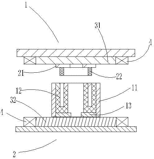
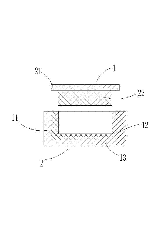
[0024] A device for NdFeB automatic pressing and orientation molding, comprising a fixed mold 1, a movable mold 2 matching the fixed mold 2, an electromagnet for providing an orientation magnetic field, and an excitation coil 4 wound on the electromagnet , the fixed mold 1 includes a metal mold case 11 and a rubber mold 12 arranged in the metal mold case 11, and the movable mold 2 includes a steel upper pressure head 21 and a rubber fixed under the steel upper pressure head 21 Upper pressing head 22.

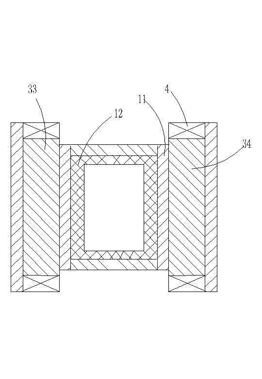
[0025] Wherein, the electromagnet includes a left electromagnet 33 and a right electromagnet 34, the left electromagnet 33 is fixed on the left side of the metal mold cover 11, and the right electromagnet 34 is fixed on the metal mold cover 11 On the right side of the upper side, the steel upper pressure head 21 is a non-magnetic steel upper pressure head, and the lower side of the metal mold cover 11 can be used as a steel lower pressure head 13, and the steel lower pressure he...

Embodiment 3

[0029] A method for pressing NdFeB by using the above-mentioned device, comprising the following steps: when the upper end surface of the rubber mold 12 is filled with magnetic powder, the electromagnet starts to provide an orientation magnetic field, and the upper pressing head 22 of the rubber descends, so that the magnetic powder moves in the up and down direction When compressed, the density increases to 3.9-4.1 g / cm 3 , at this time, the lower end surface of the steel upper pressure head 21 reaches the upper end surface of the rubber mold 12, and the magnet blank is subjected to pressure in three directions: up and down, left and right, and front and rear. When the density of the magnet blank reaches 4.6 grams / cm 3 —4.7 g / cm 3 When the orientation magnetic field drops to zero, a demagnetization magnetic field is provided. After the demagnetization magnetic field drops to zero, the upper pressing head 22 of the rubber rises, and the magnet blank is sucked out from the rubb...


PUM


Abstract

The invention discloses a device of neodymium iron boron automatic suppressing orientation forming. The device of the neodymium iron boron automatic suppressing orientation forming comprises a fixed mould, a movable mould, an electromagnet and a magnet exciting coil. The fixing mould comprises a metal mould sleeve and a rubber mould arranged in the metal mould sleeve. The movable mould comprises a steel upper pressing head and a rubber upper pressing head fixed below the steel upper pressing head. A method is further provided at the same time. The method includes the following steps that the rubber upper pressing head drops when the upper end surface of the rubber mould is filled by magnetic powder. An orientation magnetic field drops to zero when density of a magnet blank meets the requirement. A demagnetization magnetic field is provided and the demagnetization magnetic field drops to zero. Production cost is reduced. Demoulding is simple. Pressure can be improved when the device of neodymium iron boron automatic suppressing orientation forming is pressed. The problem of demoulding is not needed to be worried about. The prior isostatic pressing process can be achieved at the same time when the device of neodymium iron boron automatic suppressing orientation forming is pressed. Two steps of the existing technology on the same platform device are achieved. Production efficiency is greatly improved.

Description

technical field [0001] The invention relates to a device and method for automatic pressing and orientation molding of NdFeB. Background technique [0002] The existing domestic NdFeB pressing and orientation forming is all metal mold forming, and then the blank is put into the latex sleeve and then sent to isostatic pressing. Since the friction between the metal mold and the magnet will increase greatly with the increase of the magnet density, resulting in It is more difficult to demould, so it needs to go through a mold release agent, otherwise the mold will be easily damaged. Mold release agent must be sprayed before each work, and then the mold cavity must be cleaned frequently, otherwise the product is easy to crack. Moreover, in the production process, one person often weighs the material, one person adds the material, and one person puts the blank into latex gloves, and then sends it to isostatic pressing, and then to sintering. Most factories use this method to carry...

Claims


Application Information

Patent Timeline
IPC IPC(8): B22F3/03H01F1/057
Inventor 宋小明任春德王浩周鸿波任荷芬
Owner 宁波永久磁业有限公司
Why Eureka
Try Eureka