Quick-replacing-type hob main shaft of numerically-controlled gear hobbing machine

A gear hobbing machine and hob technology, which is applied to metal processing mechanical parts, driving devices, metal processing equipment, etc., can solve the problems of high cost and complicated equipment, and achieve the effects of convenient processing, simple structure and small torsional deformation.

Active Publication Date: 2013-05-22
常州辉展金属科技有限公司
View PDF5 Cites 3 Cited by
  • Summary
  • Abstract
  • Description
  • Claims
  • Application Information

AI Technical Summary

Problems solved by technology

The patent with the publication number CN102059408A requires a hydraulic cylinder to provide power when replacing the hob cutter bar, and a hydraulic system is necessary, so the equipment is complicated and the cost is high

Method used


Image

  • Quick-replacing-type hob main shaft of numerically-controlled gear hobbing machine
  • Quick-replacing-type hob main shaft of numerically-controlled gear hobbing machine
  • Quick-replacing-type hob main shaft of numerically-controlled gear hobbing machine

Examples


Embodiment 1

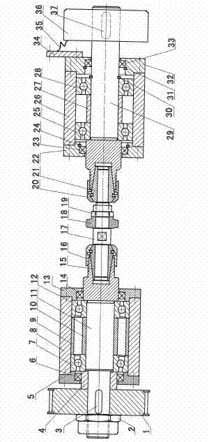
[0021] like figure 1 As mentioned above, the hob spindle of the CNC gear hobbing machine in this embodiment includes: a torque input part, a hob installation part, and an auxiliary support part, wherein the torque input shaft is located on the left and the auxiliary support part is located on the right.

[0022] The torque input components include timing pulley 1, first lock nut 2, torque input shaft key 3, spacer 4, torque input shaft 11, first angular contact ball bearing 7, second angular contact ball bearing 12, input shaft Bearing seat 8, first sealing ring 6, second sealing ring 14, first bearing end cover 5, second bearing end cover 13, large bearing adjustment sleeve 9, small bearing adjustment sleeve 10, torque input shaft elastic chuck 15 and The first pressure cap 16 used in conjunction with the elastic collet, wherein the torque input shaft elastic collet 15 is installed on one end of the torque input shaft 11, and the first locking nut 2, the synchronous pulley...

Embodiment 2

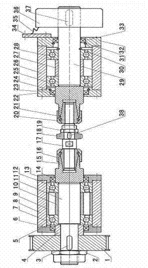
[0049] like figure 2 As shown, the torque input part and the auxiliary support part in this embodiment are the same as those of the first embodiment, the hob installation shaft key 38 is set on the hob installation shaft 17, the keyway is milled out on the hob installation shaft 17, and the hob installation shaft The key 38 is placed in the keyway, and the hob mounting shaft 17 transmits torque to the hob 18 through the hob mounting shaft key 38, which is more convenient for mounting and dismounting, and has good centering.

Embodiment 3

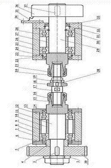
[0051] like image 3 As shown, the hob mounting member and the auxiliary supporting member in this embodiment are the same as those in Embodiment 1, and the synchronous pulley 1 in the torque input member is replaced by a gear 39 .


PUM


Abstract

The invention provides a quick-replacing-type hob main shaft structure of a numerically-controlled gear hobbing machine. According to the hob main shaft, the structure is simple and a hob can be quickly replaced. The hob main shaft comprises a torque input component, a hob installation component and an auxiliary supporting component. In terms of a hob installation shaft, what needs to be considered is hob installation, no bearings and no torque transmission parts exist on the hob installation shaft, so the structure is simple, machining is convenient, the hob and the hob installation shaft are convenient to replace, and the hob main shaft is suitable for single unit processing or small batch processing of various small module gears. In terms of torque, an auxiliary supporting shaft only bears friction torque produced by a bearing and a seal ring, and the friction torque is small, so torsional deformation of the auxiliary supporting shaft is small. A rotary encoder is installed on the auxiliary supporting shaft, the auxiliary supporting shaft and the hob installation shaft coaxially rotate, and so the rotation angle of the hob installation shaft (the hob) can be precisely detected.

Description

technical field [0001] The invention relates to a numerically controlled gear hobbing machine, in particular to a hob spindle structure of a numerically controlled gear hobbing machine. Background technique [0002] The hob of the current CNC gear hobbing machine is installed on the torque input shaft. If a hob with a different inner diameter is used, the torque input shaft must be replaced. Because the torque input shaft needs to be installed with transmission, support, sealing and other parts, the structure of the torque input shaft is complicated, the workload of replacing the torque input shaft is large, and the processing cost of the torque input shaft is high. Therefore, this hob installation method is not suitable for multi-variety, single-piece or small-batch gear processing. Publication number is CN102059408A patent, needs hydraulic cylinder to provide power when replacing hob cutter bar, must have a set of hydraulic system, so equipment is complicated, and cost is...

Claims


Application Information

Patent Timeline
Patent Type & Authority Applications(China)
IPC IPC(8): B23B19/02B23Q5/04
Inventor 丁仕燕干为民金祥曙汪蓉
Owner 常州辉展金属科技有限公司
Why Eureka
Try Eureka