Rotating table used for numerically-control machine tool

A technology of rotary table and CNC machine tools, used in manufacturing tools, metal processing equipment, metal processing machinery parts, etc.

Inactive Publication Date: 2013-05-22
JIANGSU HONGDA NUMERICAL CONTROL TECH CO LTD
View PDF5 Cites 12 Cited by
  • Summary
  • Abstract
  • Description
  • Claims
  • Application Information

AI Technical Summary

Problems solved by technology

The rotary table of the two structures mentioned above realizes the indexing movement of the table by the rotary drive device, and the table is positioned by the pin or the toothed plate. The existing types of rotary tables generally have complex structures and small spaces. , Difficulty in maintenance and adjustment, can not simultaneously achieve equal division and differential division and other defects. At the same time, the rotary table in the prior art uses many intermediate transmission mechanisms, resulting in a decrease in transmission accuracy and low transmission efficiency

Method used


Image

  • Rotating table used for numerically-control machine tool
  • Rotating table used for numerically-control machine tool

Examples


Embodiment Construction

[0013] In order to make the content of the present invention easier to understand clearly, the following further describes the present invention in detail based on specific embodiments and in conjunction with the accompanying drawings.

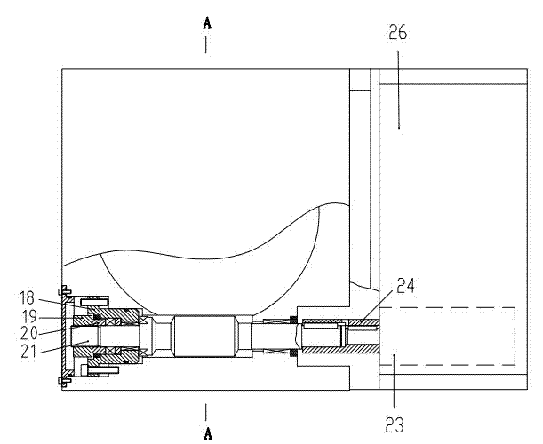
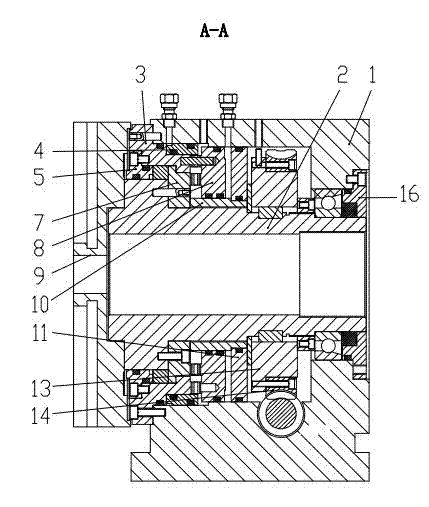
[0014] Such as figure 1 , 2 As shown, a rotary table for a CNC machine tool includes a box body 1, a front end cover 5, a rear end cover 16, a main shaft 2, a table surface 9, a three-gear ring meshing mechanism and a cylinder 4, and a driving mechanism that drives the main shaft 2 to rotate, The three-gear meshing mechanism includes an outer gear 3, an inner gear 7 and a locking gear 8. The outer gear 3 is fixedly connected with the front end cover 5, and the inner gear 7 is sleeved on the main shaft 2 and fixedly connected with the main shaft 2. The locking gear ring 8 is sleeved on the main shaft 2 through the gear ring inner sleeve 10, the front end cover 5 and the rear end cover 16 are fixedly connected to the box 1, and the main shaft 2 is ...


PUM


Abstract

The invention discloses a rotating table used for a numerically-control machine tool. The rotating table comprises a box body, a front end cover, a rear end cover, a main shaft, a working table facet, a three-gear-ring meshing mechanism, an oil cylinder and a driving mechanism driving the main shaft to rotate. The three-gear-ring meshing mechanism comprises an external gear ring, an internal gear ring and a locking gear ring, wherein the external gear ring is fixedly connected with the front end cover, the internal gear ring is sleeved on the main shaft and is fixedly connected with the main shaft, and the locking gear ring is sleeved on the main shaft through the internal gear ring. The front end cover and the rear end cover are both fixedly connected with the box body. The main shaft is rotatably supported on the front end cover and the rear end cover. The working table facet is fixedly sleeved at one end of the main shaft. The oil cylinder is connected with the locking gear ring so that the locking gear ring axially moves on the main shaft to be meshed with or detached from the external gear ring and the internal gear ring. The driving mechanism comprises a worm wheel assembly, a worm, a coupler and a motor, wherein an output shaft of the motor is fixedly connected with one end of the worm through the coupler, and the worm wheel assembly is sleeved on the main shaft. A transmission portion of the rotating table is simple in structure, several middle transmission links are eliminated, the motor directly drives the worm to rotate, transmission precision is improved, and transmission efficiency is improved.

Description

technical field [0001] The invention relates to a rotary worktable for a numerical control machine tool, which is used for a numerical control machining center, a numerical control gantry milling, a multifunctional compound numerical control processing and a special machine tool. Background technique [0002] At present, the rotary table is installed on a rotary multi-station machine tool, and is used to complete multiple processes of parts at one time. The rotary table commonly used in the machining industry usually has the following types: one is to drive the camshaft to rotate through the motor, and then drive the pin shafts evenly distributed under the table to make the table index, and the switch will send a signal when it is in place. Then the workbench is positioned by the pin or the toothed plate; the second is to turn the worktable through the rotary cylinder, and the switch sends a signal after it is in place, and then the workbench is positioned by the bolt or th...

Claims


Application Information

Patent Timeline
Patent Type & Authority Applications(China)
IPC IPC(8): B23Q1/26B23Q1/44B23Q16/10
Inventor 许云龙吴华平杨俊召
Owner JIANGSU HONGDA NUMERICAL CONTROL TECH CO LTD
Why Eureka
Try Eureka