Liquid sulphur degassing device and liquid sulphur degassing method

A liquid sulfur degassing and liquid sulfur technology, applied in chemical instruments and methods, sulfur compounds, inorganic chemistry, etc., can solve problems such as increased consumption of additives, impact on product quality, and difficulty in operation, so as to improve recovery and production efficiency. The effect of high, low equipment investment

Active Publication Date: 2013-05-22
ZHENHAI PETROCHEMICAL ENG CO LTD
View PDF5 Cites 35 Cited by
  • Summary
  • Abstract
  • Description
  • Claims
  • Application Information

AI Technical Summary

Problems solved by technology

H in the liquid sulfur of this method 2 S can meet the requirement of less than 10ppm (w), and the tail gas can recover sulfur after removal, but the process is complicated, the investment is large, and the operation is difficult, and the tail gas in the liquid sulfur tank must also be pumped by the injection system to the tail gas incinerator of the sulfur recovery device for incineration
[0007] The liquid sulfur stirring + additive method has a simple process, but the product quality is affected by the additive, the on-site operating environment is poor, there are many equipment failures, and the consumption of additives is also increased

Method used


Image

  • Liquid sulphur degassing device and liquid sulphur degassing method

Examples


Embodiment Construction

[0023] The present invention will be further described in detail below in conjunction with the accompanying drawings and embodiments.

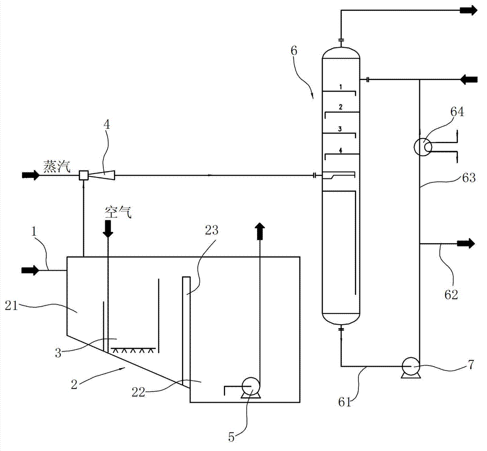
[0024] The liquid sulfur degassing device includes:

[0025] The liquid sulfur pipeline 1 is used to transport the liquid sulfur to be treated, one end of which is connected to the liquid sulfur discharge end of the sulfur recovery device, and the other end is inserted into the gas stripping tank 21 so that its outlet is close to the bottom of the gas stripping tank 21.

[0026] The liquid sulfur pool 2 includes a gas stripping pool 21 and a finished product pool 22 . The depth of the air stripping pool 21 in this embodiment is less than the depth of the finished product pool 22, and the bottom surface of the air stripping pool 21 is an inclined structure, that is, it is inclined downward from the outside of the air stripping pool 21 to the finished product pool 22, so that the liquid sulfur The deposition of solid sulfur in the medium. An o...


PUM

PropertyMeasurementUnit
heightaaaaaaaaaa

Abstract

The invention relates to a liquid sulphur degassing device and a liquid sulphur degassing method. The liquid sulphur degassing device comprises a liquid sulphur tank communicated with a liquid sulphur pipeline, wherein the liquid sulphur tank is internally provided with gas stripping equipment which can strip hydrogen sulphide gas in liquid sulphur, and the upper part of the liquid sulphur tank is provided with gas pumping equipment which can pump the hydrogen sulphide gas with other gases in the liquid sulphur tank out of the liquid sulphur tank; and the liquid sulphur degassing device is characterized in that the liquid sulphur tank comprises a gas stripping tank and a finished product tank, wherein an overflow dam is arranged between the gas stripping tank and the finished product tank; the liquid sulphur pipeline is communicated with the gas stripping tank; the suction inlet of the liquid sulphur pump is connected with the bottom of the finished product tank; the outlet of the gas pumping equipment is connected with the material inlet of an absorption tower; and the top of the absorption tower is provided with a waste gas outlet, the upper part of the absorption tower is provided with an absorption liquid inlet, a liquid outlet arranged at the bottom of the absorption tower is connected with a main pipeline, and the main pipeline is provided with a pressure pump which pumps out, pressurizes and conveys the liquid in the absorption tower. The liquid sulphur degassing device provided by the invention is simple in process, low in equipment investment and good in degassing effect.

Description

technical field [0001] The invention relates to the field of sulfur recovery, in particular to a liquid sulfur degassing device and method capable of recovering sulfur. Background technique [0002] The liquid sulfur produced by the sulfur recovery unit generally contains 300ppm of H 2 S, if it leaves the factory in the form of liquid sulfur, during the transportation process H 2 S is easy to cause agglomeration, when H in the air 2 When the S content reaches 3.4%, it reaches the H 2 The explosion limit of S, and the steel container itself contains FeS, a substance that is easy to catch fire. At this time, the conditions for explosion are met, so there are potential safety hazards; , H 2 S will escape and pollute the environment, the unescaped H 2 S remains in the solid sulfur, which will cause secondary pollution during the user's use. Therefore, no matter whether the sulfur leaves the factory in solid or liquid form, the H in the liquid sulfur must be 2 S removed. ...

Claims


Application Information

Patent Timeline
Patent Type & Authority Applications(China)
IPC IPC(8): C01B17/027
Inventor 朱元彪冯卫权杨相益陈奎吴国勤钱志海黄卫存励国辉
Owner ZHENHAI PETROCHEMICAL ENG CO LTD
Why Eureka
Try Eureka