
Steam heavy oil thermal recovery equipment and method thereof

An equipment and technology for heavy oil, which is applied in the field of equipment for steam thermal recovery of heavy oil, can solve the problems of depth limitation, high power consumption, and steam channeling in non-oil layers of ground steam injection thermal recovery technology, and achieves improved viscosity reduction and thermal recovery. Displacement effect, the effect of reducing the consumption of electric energy and improving the degree of recovery

Active Publication Date: 2013-05-22
CHINA NAT OFFSHORE OIL CORP +1
View PDF7 Cites 5 Cited by
  • Summary
  • Abstract
  • Description
  • Claims
  • Application Information

AI Technical Summary

Problems solved by technology

[0003] The downhole electric heating technology is to lower the heating cable into the well with the oil pipe, and heat the heavy oil around the heating cable after the electricity is turned on. The problem of this technology is that it consumes a lot of power and the range of heat spread is small, so it has been rarely used at present.
[0005] (1) During the process of steam injection from the surface along the wellbore, the steam may leak from the casing thread along the way to the non-oil zone, causing steam channeling in the non-oil zone. Well and cementing technology requirements are high;
[0006] (2) Although many heat insulation measures have been taken in the wellbore, the heat loss during steam injection is generally between 30% and 40%, resulting in a huge waste of energy;
[0007] (3) Due to the relatively large heat loss during the steam injection process, the surface steam injection thermal recovery technology is limited in depth
[0008] (4) Due to the huge steam generation equipment on the ground, the application in offshore oil fields and some marginally limited places is limited;
[0009] (5) The combustion product of the ground heating device will cause great pollution to the environment;
[0010] (6) Heat insulation protection equipment needs to be used during the development process, resulting in increased development costs

Method used


Image

  • Steam heavy oil thermal recovery equipment and method thereof
  • Steam heavy oil thermal recovery equipment and method thereof
  • Steam heavy oil thermal recovery equipment and method thereof

Examples


Embodiment Construction

[0042] Embodiments of the present invention will be described in detail below in conjunction with the accompanying drawings. It should be noted that, in the case of no conflict, the embodiments in the present application and the features in the embodiments can be combined arbitrarily with each other.

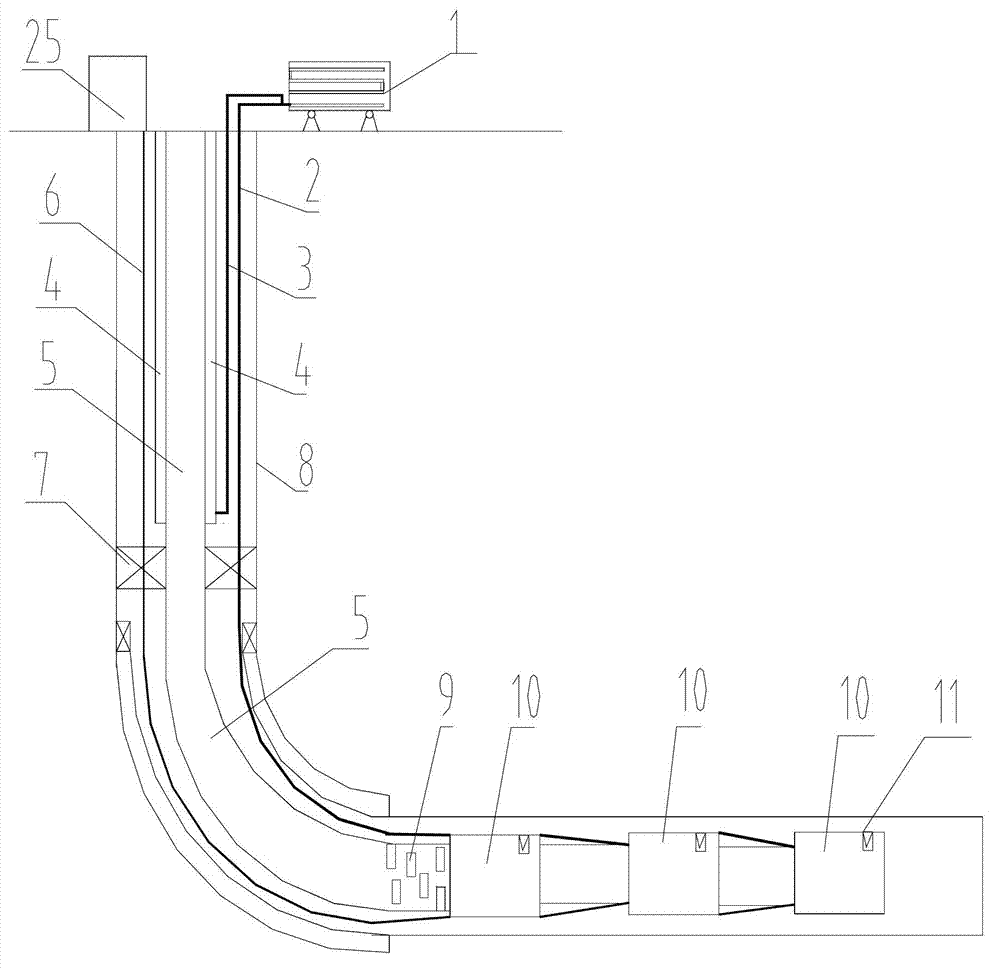
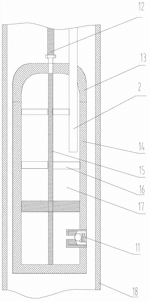
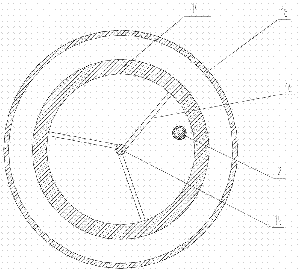
[0043] The steam heat recovery equipment of heavy oil in the embodiment of the present invention is realized in this way, see figure 1 Shown, this equipment comprises ground device and downhole device, and surface device comprises solar water heater 1 and transformer 25, and downhole device comprises three steam generators 10, and the upper end of water pipe 2 is connected with solar water heater 1, and the upper end of cable 6 is connected with transformer 25, the wellbore 8 includes a vertical well section, a deflected well section and a horizontal section, the oil pipe 5, the water delivery pipe 2 and the cable 6 enter the wellbore 8 together, and extend to the horizontal wel...


PUM


Abstract

Steam heavy oil thermal recovery equipment comprises a ground device and a downhole device. The downhole device comprises at least one steam generator. The steam heavy oil thermal recovery equipment further comprises an oil pipe, a water delivering pipe and a cable, wherein the upper ends of the oil pipe, the water conveying pipe and the cable are connected with the ground device, the oil pipe, the water conveying pipe and the cable in a wellhole extend to a horizontal well section, the lower end of the oil pipe is positioned in an oil layer, and the lower ends of the water delivering pipe and the cable are respectively connected with the steam generators which are arranged above or in the oil layer. The invention further provides a method for steam heavy oil thermal recovery. Steam generated by the steam generators in an embodiment of the steam heavy oil thermal recovery equipment is directly used for heating heavy oil, temperature of the steam can be increased, recovering degree of the heavy oil is greatly improved, the steam is not required to be delivered to the oil layer section from the ground via the wellhole, so that steam leakage and heat loss during delivering are avoided. And the steam heavy oil thermal recovery equipment and the method thereof are particularly applicable to offshore oilfields and other fields with limited borders.

Description

technical field [0001] The invention relates to an oil extraction equipment, in particular to an equipment and method for steam thermal recovery of heavy oil. Background technique [0002] At present, the development of heavy oil reservoirs is basically based on thermal recovery, mainly including steam huff and puff, steam flooding, oil layer combustion technology, downhole electric heating technology and multi-component thermal fluid technology that has been successfully applied offshore. [0003] The downhole electric heating technology is to lower the heating cable into the well with the oil pipe, and heat the heavy oil around the heating cable after the electricity is turned on. The problem of this technology is that it consumes a lot of power and the range of heat spread is small, so it has been seldom used at present. [0004] The current leading technologies for thermal recovery are steam huff and puff and steam flooding. The basic principle is to generate high-temper...

Claims


Application Information

Patent Timeline
Patent Type & Authority Applications(China)
IPC IPC(8): E21B43/24
Inventor 董社霞张海龙张保康季公明刘新峰王圣虹李效波朱春明周欢
Owner CHINA NAT OFFSHORE OIL CORP
Learn More