Urea solution metering injector and control method thereof

A solution and urea technology, which is applied to the electronic control of exhaust gas treatment devices, noise reduction devices, exhaust devices, etc., can solve the problems of difficult flow of urea solution, fluctuation of urea solution pressure amplitude, etc., so as to improve control accuracy and prevent device rupture. , the effect of reducing pressure fluctuations

Inactive Publication Date: 2013-05-22
JIANGSU UNIV
View PDF5 Cites 7 Cited by
  • Summary
  • Abstract
  • Description
  • Claims
  • Application Information

AI Technical Summary

Problems solved by technology

The flow control of the urea solution is to obtain the pressure of the urea solution through the pressure sensor inside the urea solution supply system, and then control the flow of the urea solution by controlling the opening time of the nozzle, and the principle of the urea s

Method used


Image

  • Urea solution metering injector and control method thereof
  • Urea solution metering injector and control method thereof

Examples


Example Embodiment

[0022] The present invention will be further described below in conjunction with the drawings and specific implementations of the specification.

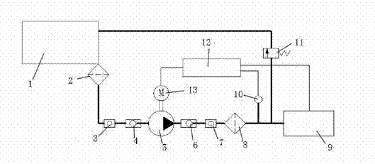
[0023] Such as figure 1 As shown, a urea solution metering and spraying device includes a pump 5, a urea tank 1, a stepping motor 13, and a nozzle 9. It is characterized in that the outlet of the urea tank 1 sequentially passes through a pre-filter 2, a first variable volume The part 3 and the first check valve 4 are connected to the inlet end of the pump 5, and the output end of the pump 5 is sequentially connected to the nozzle 9 through the second check valve 6, the second variable volume part 7 and the filter 8 A stepping motor 13 is connected to the pump 5; a pressure valve 11 is provided between the filter 8 and the nozzle 9; a sensor 10 is provided between the nozzle 9 and the filter 8. The stepping motor 13 is connected to a control unit 12, and the control unit 12 is connected to the sensor 10 and the nozzle 9. The control un...


PUM


Abstract

The invention discloses a urea solution metering injector which comprises a pump, a urea cylinder, a step motor and a nozzle. An outlet of the urea cylinder is connected to an entry end of the pump sequentially through a pre-filter, a first volume-variable member and a first one-way valve, a discharge end of the pump is connected to the nozzle sequentially through a second one-way valve, a second volume-variable member and a filter, and the step motor is connected to the pump. A pressure valve is disposed between the filter and the nozzle. A sensor is disposed between the nozzle and the filter. The step motor is connected with a control unit which is connected with the sensor and the nozzle. The control unit is used for controlling pressure and starting time of urea solution from the nozzle according to the speed of the step motor. Each of the pre-filter, the filter, the first one-way valve, the second one-way valve, the pump and the step motor is provided with a heating unit.

Description

technical field [0001] The invention relates to a solution injection device and a control method thereof, in particular to a urea solution metering injection device and a control method thereof. Background technique [0002] Diesel engine is the model with the highest thermal efficiency, the best energy utilization rate and the most energy-saving model among various power machinery currently being industrialized. However, as the total amount of pollutant emissions continues to rise every year, the control of diesel engine pollutant emissions is imminent. Diesel engine emission standards set limits for harmful components in diesel engine exhaust gases such as hydrocarbons (HC), nitrogen oxides (NOX), carbon monoxide (CO) and particulate matter (PM), among which nitrogen oxides are very difficult to deal with. At present, the commonly used post-treatment methods of nitrogen oxides include selective catalytic reduction, selective catalytic reduction of hydrocarbons, nitrogen o...

Claims


Application Information

Patent Timeline
IPC IPC(8): F01N3/20F01N9/00
CPCY02T10/47Y02T10/40
Inventor 陈强王谦王荣誉何志霞田东波吴志新
Owner JIANGSU UNIV
Why Eureka
Try Eureka