
Drying machine based on mineral drying agent form

A desiccant and dryer technology, applied in the direction of dryers, drying solid materials, drying chambers/containers, etc., can solve the problems of inconvenient replacement of desiccants, uncontrollable humidity, large space occupation, etc., and achieve more humanized operation , realize the effect of intelligent precision control humidity, easy installation and configuration

Inactive Publication Date: 2013-05-22
东莞市誉能五金制品有限公司
View PDF9 Cites 4 Cited by
  • Summary
  • Abstract
  • Description
  • Claims
  • Application Information

AI Technical Summary

Problems solved by technology

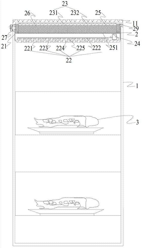
[0006] The purpose of the present invention is to disclose a dryer based on a mineral desiccant, which solves the problems of large floor space, inability to control humidity, inconvenient replacement of desiccant, failure of desiccant due to uneven heating, and impact on the object to be dried during heating

Method used


Image

  • Drying machine based on mineral drying agent form
  • Drying machine based on mineral drying agent form
  • Drying machine based on mineral drying agent form

Examples


Embodiment 1

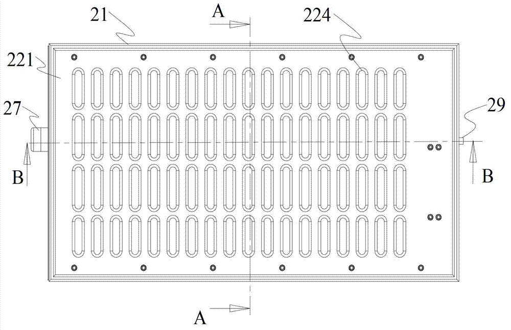
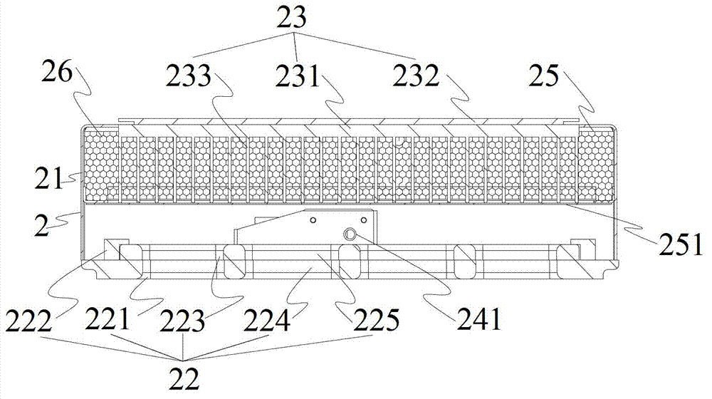
[0036] Such as Figure 1 to Figure 5 As shown, embodiment one is based on a mineral desiccant dryer, including a container 1 (such as a cabinet, a bottle, etc.) for accommodating the object to be dried 3 and having a container door (not shown), A container humidity sensor (not shown), a container door status sensor (not shown) for sensing container door opening or closing, a micro control unit MCU (not shown) and a drying device 2 on the top of the container The drying device 2 includes a sealed box body 21, a moisture absorption door 22 located at the bottom of the box body, a driving device (ie, a motor 24 or other power devices, such as electromagnetic power, etc.) that drives the moisture absorption door 22 to open or close, for A hygroscopic door status sensor (not shown) for sensing the opening or closing of the moisture-absorbing door 22, a heating unit 23 arranged on the top of the box body, a temperature sensor (not shown) arranged on the heating unit, and a temperatu...

Embodiment 2

[0045] Such as Figure 6 to Figure 10 As shown, Embodiment 2 is based on a dryer of mineral desiccant type. The cross section of the container 1 is a circular structure, and the drying device 2 is a circular drying device; The moving piece 223 is driven to rotate around the central axis 28, so that the hole 224 of the fixed piece and the hole 225 of the moving piece are aligned or staggered; other structures of the second embodiment are the same as those of the first embodiment.

[0046] In the second embodiment, the moving piece 223 is sleeved on the central shaft 28, and the moving piece holder 222 may not be needed; the central shaft 28 is connected to the motor 24, so that the motor 24 drives the moving piece 223 to rotate around the central shaft 28; When the moving piece 223 turns to the holes of the moving piece hole 225 and the fixed piece hole 224 to overlap to form an airflow passage; Its airflow path is disconnected. The moving plate holes 225 are arranged in a ci...


PUM


Abstract

The invention discloses a drying machine based on a mineral drying agent form. The drying machine based on the mineral drying agent form is used for containing dried objects and is provided with a container with a container door, a container humidity sensor which is arranged inside the container, a container door state sensor used for sensing opening or closing of the container door, a micro control unit (MCU) and a drying device which is arranged on top of the container. According to the drying machine based on the mineral drying agent form, the structure is adopted, and the drying device is installed on the upper portion of a dried container. According to a principle that water vapor is lighter than air, the installation mode is optimal in water vapor absorption, and the container using space can be further and effectively saved. The drying machine based on the mineral drying agent form is small in occupied space size and convenient to install, and drying agent heating reduction does not affect the temperature of the dried objects.

Description

technical field [0001] The invention relates to the field of dryers, in particular to a dryer based on mineral desiccant. Background technique [0002] Existing general-purpose small-scale drying equipment is usually divided into two categories: [0003] 1. Refrigeration and dehumidification, drying by condensing water vapor, this type of equipment structure usually occupies a large volume, high energy consumption, dehumidification needs drainage, and is also limited by temperature. When the temperature is lower than 5 degrees Celsius, the condenser It is easy to freeze, block the dehumidification air duct, and make the dehumidification equipment invalid. [0004] 2. Desiccant dehumidification, desiccant dehumidification is divided into desiccant package and desiccant regeneration dehumidification equipment. The desiccant bag is easy to use and has obvious effects, but the biggest problem with the desiccant bag is that it cannot control the humidity, it can only be estimat...

Claims


Application Information

Patent Timeline
IPC IPC(8): F26B25/08F26B25/22F26B5/16
Inventor 倪军
Owner 东莞市誉能五金制品有限公司
Learn More