Methods for the analysis of signal transmission and switching characteristics in fiber gratings or similar fiber gratings
A fiber grating and signal transmission technology, applied in the field of optical information, can solve the problem of wasting fiber bandwidth resources
- Summary
- Abstract
- Description
- Claims
- Application Information
AI Technical Summary
Problems solved by technology
Method used
Image
Examples
Embodiment Construction
[0085] Embodiments of the present invention will be described in detail below in conjunction with the accompanying drawings.
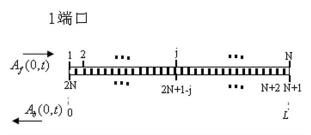
[0086] In this example, if image 3 As shown, assuming that the light is only input at port 1, because the reflection starts from the end of the grating, the boundary condition is A f (0,t)=1, 3kw 1 / 2 , A b (L,t)=0 (indicating no reflected signal at the tail of the grating). Assume that the grating has no energy inside at the initial moment, that is, A f,b (z,0)=0. Choose γ=0.1W -1 cm -1 ,λ B =1.55μm,t=4000ps,v g =2.06×10 8 m / s. Figure 4(a) shows the fiber grating at the input amplitude A=1, 3kw 1 / 2 In the case of , the nonlinear transmittance curve varies with the amount of detuning. When the input power is low, the transmittance curve is symmetrical about the detuning amount δ, but as the input power increases, the nonlinear effect causes the band gap to shift to a lower frequency, and the transmittance curve is no longer about the detuni...
PUM
 Abstract
Description
Claims
Application Information
 - R&D
- Intellectual Property
- Life Sciences
- Materials
- Tech Scout
- Unparalleled Data Quality
- Higher Quality Content
- 60% Fewer Hallucinations
Browse by: Latest US Patents, China's latest patents, Technical Efficacy Thesaurus, Application Domain, Technology Topic, Popular Technical Reports.
© 2025 PatSnap. All rights reserved.Legal|Privacy policy|Modern Slavery Act Transparency Statement|Sitemap|About US| Contact US: help@patsnap.com


