Radio frequency band selecting repeater station resisting to self-excitation interference and method of reducing self-excitation interference

A repeater and band selection technology, applied in the field of radio frequency repeaters, can solve problems such as self-excited interference, inability to cope with band selection, and radio frequency repeaters cannot work normally, and achieves the effect of wide application

Active Publication Date: 2013-05-22
福建京奥通信技术有限公司
View PDF4 Cites 2 Cited by
  • Summary
  • Abstract
  • Description
  • Claims
  • Application Information

AI Technical Summary

Problems solved by technology

Generally speaking, a high-gain RF repeater can improve network quality more effectively, but since the signal amplified by the RF repeater is in the same frequency band as the received signal, if the gain is greater than the antenna isolation, it will constitute a self-excited Interference, causing the radio frequency repeater to fail to work normally, and seriously affecting the signal quality
[0003] In order to ensure good network communication quality, engineering applications require that the amplified signal reaching the receiving antenna end, that is, the self-excited interference signal y(t) is 15dB smaller than the original signal s(t). To meet the above requirements, traditional RF repeaters are usual

Method used


Image

  • Radio frequency band selecting repeater station resisting to self-excitation interference and method of reducing self-excitation interference
  • Radio frequency band selecting repeater station resisting to self-excitation interference and method of reducing self-excitation interference
  • Radio frequency band selecting repeater station resisting to self-excitation interference and method of reducing self-excitation interference

Examples


Embodiment Construction

[0027] In order to further explain the technical solution of the present invention, the present invention will be described in detail below through specific examples.

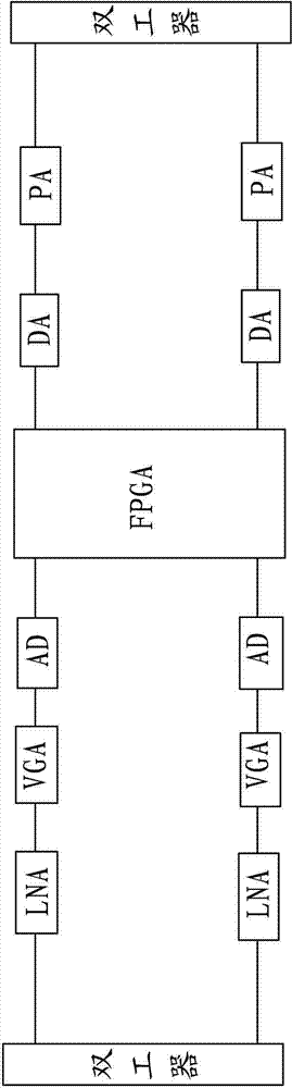
[0028] A kind of anti-self-excited interference radio frequency band selection repeater related to the present invention, its overall principle diagram is the same as figure 1 Similar, so it will not be described in detail, that is, it may also include components such as a duplexer, a low noise amplifier LNA, an adjustable gain amplifier VGA, an analog-to-digital converter AD, an FPGA circuit, a digital-to-analog converter DA, and a power amplifier PA.

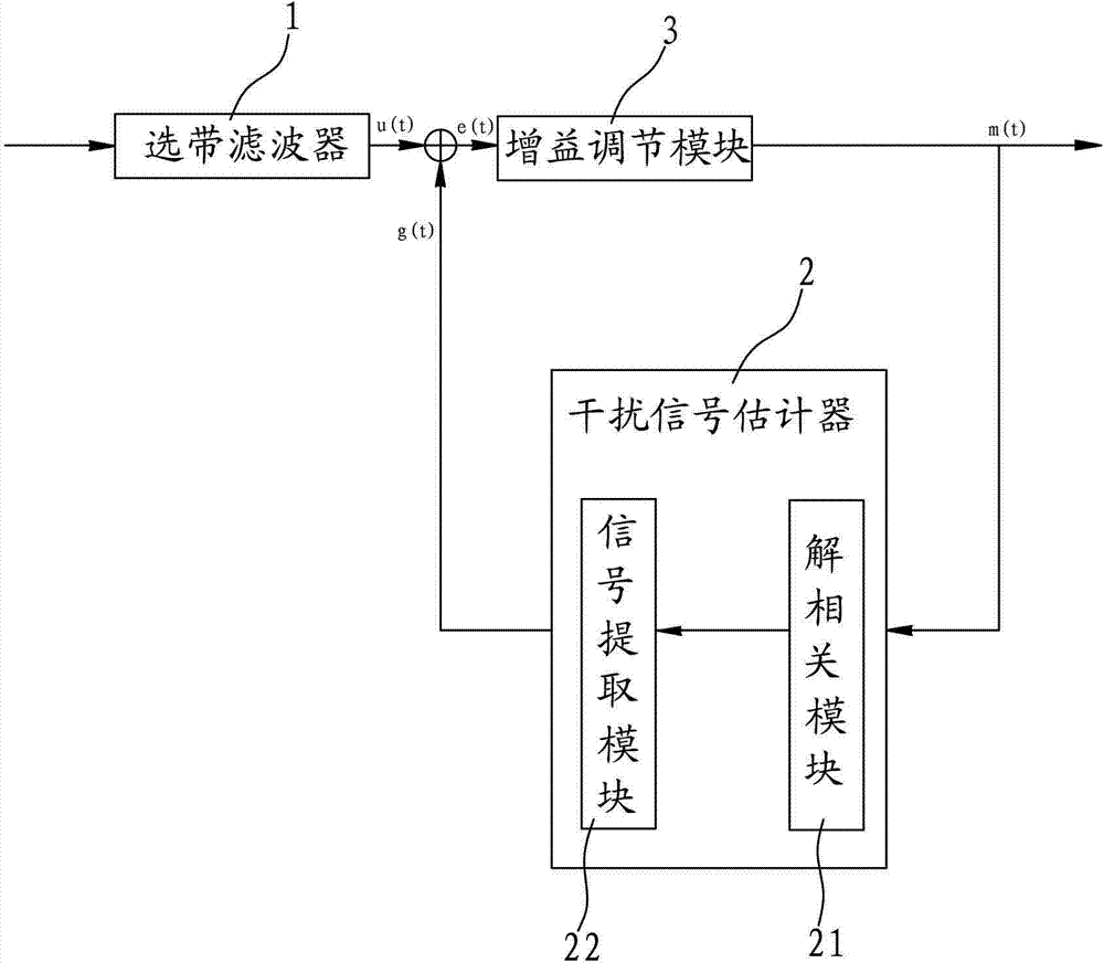
[0029] Such as figure 1 As shown, the present invention is characterized in that: the FPGA circuit has a band selection filter 1, an interference signal estimator 2 and a gain adjustment module 3, wherein the FPGA is a field programmable logic array, and the band selection filter 1 receives and outputs The initial signal u (t) that contains original signal s (...


PUM


Abstract

The invention discloses a radio frequency band selecting repeater station resisting to self-excitation interference and a method of reducing the self-excitation interference. The radio frequency band selecting repeater station is provided with a field programmable gate array (FPGA) circuit. The FPGA circuit is provided with a band selecting filter, an interference signal estimator, and a gain adjustment module, wherein the band selecting filter receives and outputs initial signals containing original signals and self-excitation interference signals, the interference signal estimator is provided with a decorrelation module and a signal extraction module, the signal extraction module is connected with the decorrelation module and generates approaching signals at an output end of the signal extraction module, an input end of the gain adjustment module receives difference signals formed by subtracting the initial signals and the approaching signals, and the decorrelation module is connected with an output end of the gain adjustment module and removes relativity of output signals. Compared with the prior art, the radio frequency band selecting repeater station does not need high installation cost, can conduct self-excitation treatment on frequency spectrum time-varying global system for mobile communications (GSM) due to the fact that understanding relevant processing treatment is conducted, and has the function of being wide in application range.

Description

technical field [0001] The present invention relates to the field of radio frequency repeaters, more specifically to a radio frequency band selection repeater that resists self-excited interference and a method for reducing self-excited interference of radio frequency band selection repeaters, which can be applied to time-varying frequency spectrum selection With GSM on. Background technique [0002] By re-amplifying the received wireless signal, the repeater can improve the signal quality of the base station signal without coverage or weak coverage area, and finally effectively improve the voice call service and data transmission service; among them, the radio frequency repeater has low installation difficulty and Features of strong applicability. Generally speaking, a high-gain RF repeater can improve network quality more effectively, but since the signal amplified by the RF repeater is in the same frequency band as the received signal, if the gain is greater than the ant...

Claims


Application Information

Patent Timeline
IPC IPC(8): H04B7/15H04B1/10
Inventor 谢东福康忠林卓开泳
Owner 福建京奥通信技术有限公司
Why Eureka
Try Eureka