DMA controller and data readout device
A DMA controller and data technology, applied in electrical digital data processing, instruments, memory systems, etc., can solve problems such as increased CPU burden
- Summary
- Abstract
- Description
- Claims
- Application Information
AI Technical Summary
Problems solved by technology
Method used
Image
Examples
Embodiment approach 1
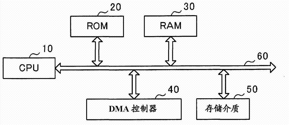
[0037] figure 1 It is a block diagram showing the configuration of a data readout device including a DMA controller according to Embodiment 1 of the present invention. This data readout device is installed, for example, in equipment (a so-called data logger) that is connected to a plurality of power conditioners in a solar power generation system and collects data related to the operating status of each power conditioner.
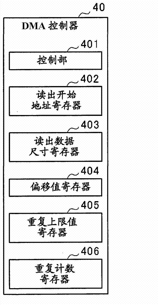
[0038] like figure 1 As shown, the data readout device includes CPU (Central Processing Unit, central processing unit) 10, ROM (Read Only Memory, read only memory) 20, RAM (Random Access Memory, random access memory) 30, DMA (Direct Memory Access) controller 40 , and storage medium 50 , and each component is connected to each other via bus 60 .
[0039] The CPU 10 controls the operation of the entire device including the data readout device based on various programs, data, and the like stored in the ROM 20 . The RAM 30 is used as a work memory or the lik...
Embodiment approach 2
[0055] Next, a DMA controller according to Embodiment 2 of the present invention will be described. The DMA controller of the second embodiment is also included in the same data readout device as that of the first embodiment. In addition, the same code|symbol is attached|subjected to the part common to the data reading apparatus of Embodiment 1, and it demonstrates. Figure 5 It is a block diagram showing the structure of the DMA controller 40 of this embodiment. like Figure 5 As shown, in the DMA controller 40 of this embodiment, a search data register 407 is added. Data desired by the CPU 10 (for example, a sector number) is stored in the search data register 407 .
[0056] refer to Image 6 The flow chart of FIG. 1 illustrates the procedure of data read processing executed by the DMA controller 40 of this embodiment. This data reading process is also started when a predetermined control signal is output by the CPU 10 as in the first embodiment.
[0057] First, the co...
Embodiment approach 3
[0065] Next, an embodiment of the data readout device of the present invention will be described. Figure 7 It is a block diagram showing the structure of the data readout device of this embodiment. like Figure 7 As shown, the data reading device includes CPU10, ROM20, first internal memory 31, second internal memory 32, first DMA controller 41, second DMA controller 42, external memory interface 70, and external memory 51.
[0066] The CPU 10 , ROM 20 , first internal memory 31 , second internal memory 32 , first DMA controller 41 , second DMA controller 42 , and external memory interface 70 are connected to each other via an internal bus 61 . In addition, the external memory interface 70 and the external memory 51 are connected via the external bus 62 which is a serial bus. In this embodiment, a serial flash memory is used as the external memory 51 .
[0067] The CPU 10 controls the operation of the entire device including the data readout device based on various program...
PUM
 Abstract
Description
Claims
Application Information
 - R&D
- Intellectual Property
- Life Sciences
- Materials
- Tech Scout
- Unparalleled Data Quality
- Higher Quality Content
- 60% Fewer Hallucinations
Browse by: Latest US Patents, China's latest patents, Technical Efficacy Thesaurus, Application Domain, Technology Topic, Popular Technical Reports.
© 2025 PatSnap. All rights reserved.Legal|Privacy policy|Modern Slavery Act Transparency Statement|Sitemap|About US| Contact US: help@patsnap.com


