Energy-saving device of burner
An energy-saving device and burner technology, which is applied in the direction of burners, lighting and heating equipment, etc., can solve the problems of incomplete combustion, insufficient instantaneous temperature, and low thermal efficiency, so as to reduce exhaust emissions, improve thermal efficiency, and meet the requirements of cleanliness and sanitation. Effect
- Summary
- Abstract
- Description
- Claims
- Application Information
AI Technical Summary
Problems solved by technology
Method used
Image

Examples
Embodiment 1
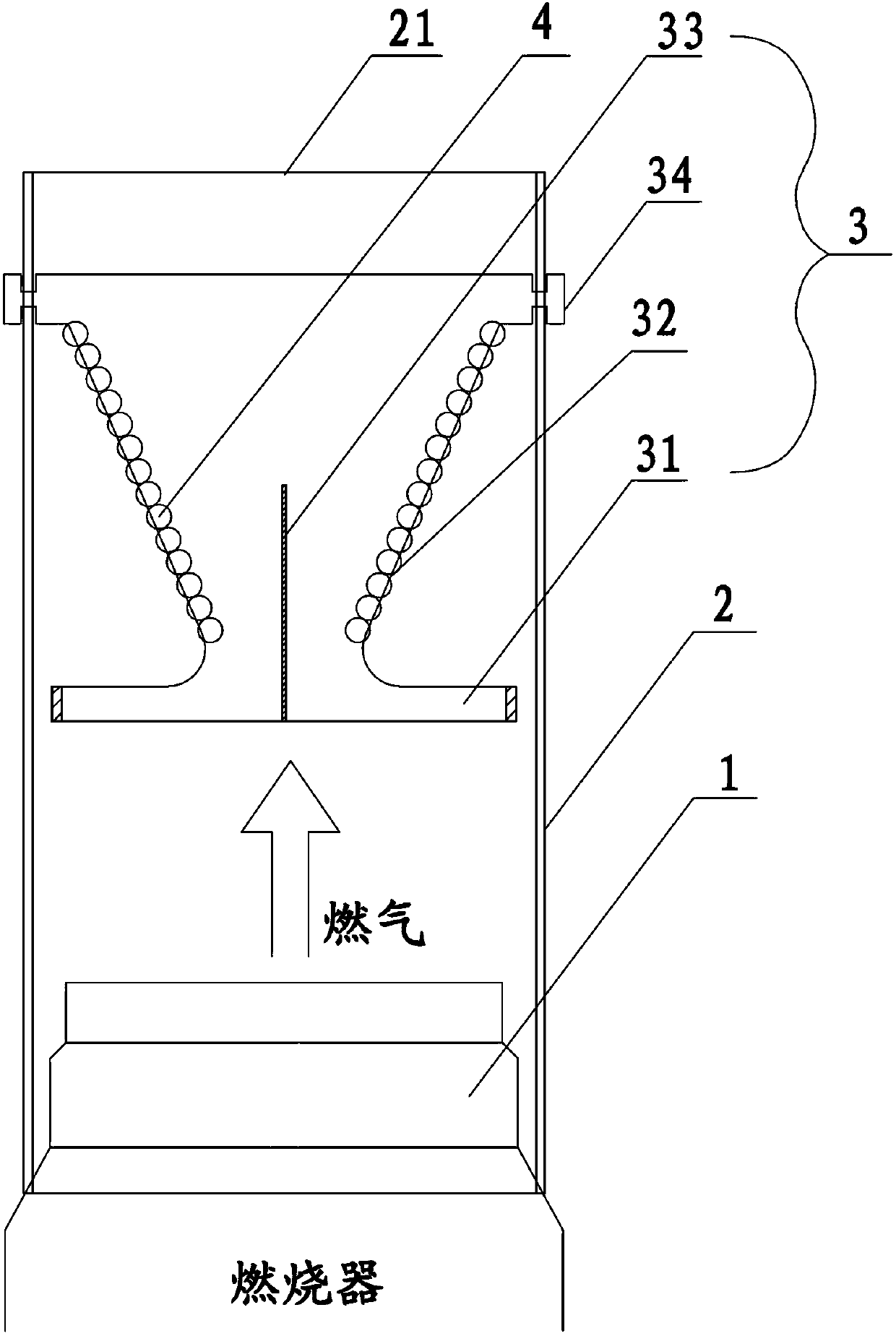
[0022] The burner energy-saving device of the present invention combines figure 1 , including the burner head 1 and the furnace cover 2, the furnace cover 2 is installed in conjunction with the burner head 1, the furnace cover 2 is a grid structure, and the grid can be any geometric hole; a bracket is installed directly in front of the burner head 1 The ring 3 and the support ring 3 are hollow structures, and the outer surface of the support ring 3 is wound with a metal wire 4, and the metal wire 4 is a heating wire.
[0023] Wherein, the bracket ring 3 includes a bracket body 32 and a buckle 34, the metal wire 4 is wound on the outer surface of the bracket body 32, the bracket body 32 is a conical hollow structure, and the cone top 32a of the bracket body 32 extends horizontally to form a bracket sheet 31; the cone bottom 32b of the bracket body 32 is provided with buckles 34, two of which are symmetrically arranged on the outer wall of the cone bottom 32b, and the bracket ri...
Embodiment 2
[0027] The burner energy-saving device of the present invention combines figure 1 , including the burner head 1 and the furnace cover 2, the furnace cover 2 is installed with the burner head 1, the furnace cover 2 is a grid structure, and two support rings 3 are installed directly in front of the burner head 1, and the support rings 3 are Hollow structure, the outer surface of the support ring 3 is wound with metal wire 4, and the metal wire 4 is made of carbon steel 33H.
[0028] which, combined with figure 2 , the bracket ring 3 includes a bracket body 32 and a buckle 34, the metal wire 4 is wound on the outer surface of the bracket body 32, the bracket body 32 is a conical hollow structure, and the cone top 32a of the bracket body 32 extends horizontally as a bracket piece 31; a buckle 34 is provided at the cone bottom 32b of the bracket body 32, and there are two buckles 34, which are symmetrically arranged on the outer wall of the cone bottom 32b, and the bracket ring 3...
Embodiment 3
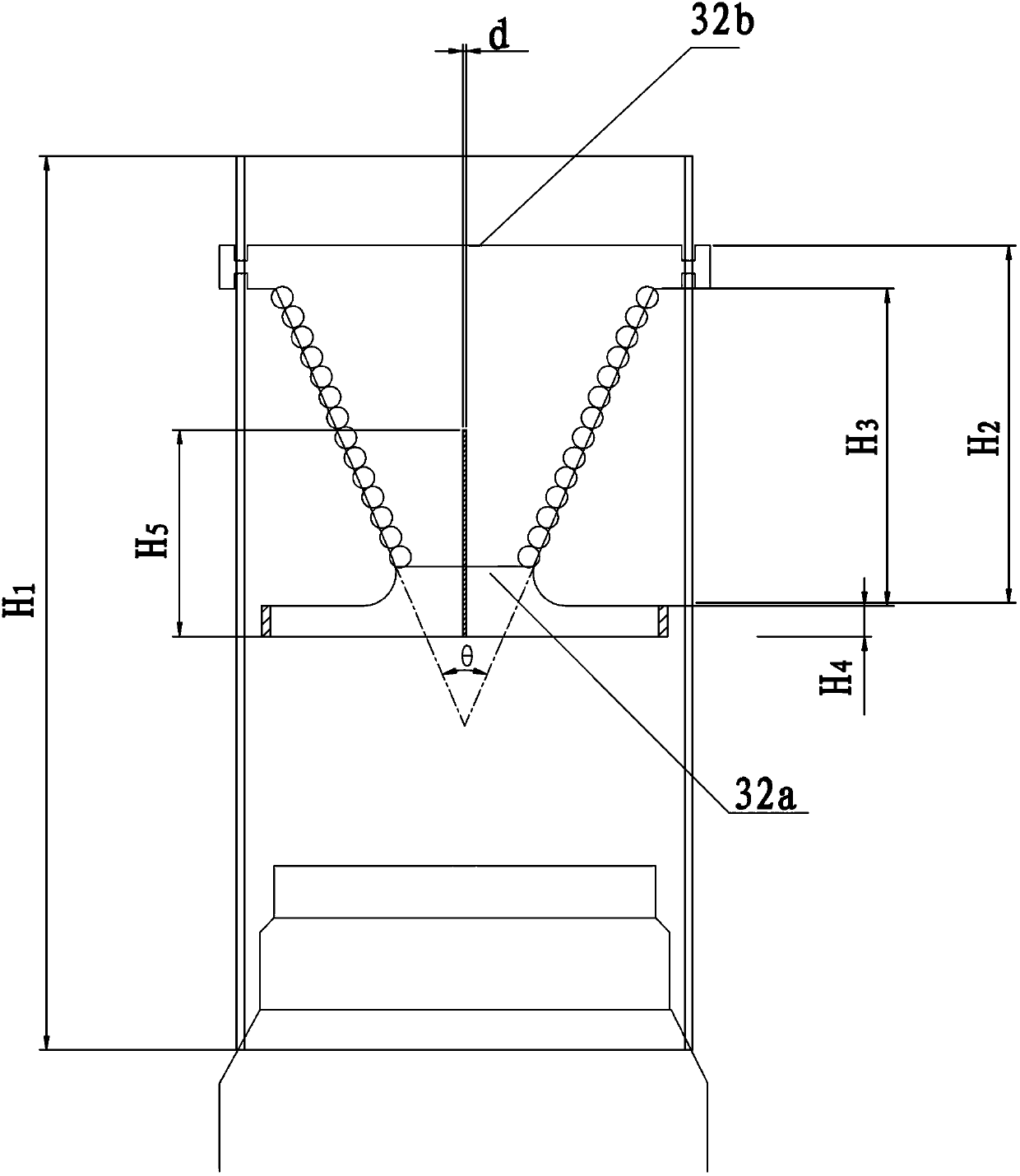
[0032] The setting and working principle of this embodiment and embodiment 1 are the same, the difference is: the height H of the furnace cover 2 1 is 150mm, the height H of the support ring 3 2 is 50mm; the height H of the bracket body 32 3 is 43mm, and the cone angle θ is 45°; the height H of the support sheet 31 4 is 3mm; the width d of the slot 34 is 0.4mm, and the height H 5 20mm.
PUM
| Property | Measurement | Unit |
|---|---|---|
| Height | aaaaa | aaaaa |
| Height | aaaaa | aaaaa |
| Cone angle | aaaaa | aaaaa |
Abstract
Description
Claims
Application Information
 - R&D
- Intellectual Property
- Life Sciences
- Materials
- Tech Scout
- Unparalleled Data Quality
- Higher Quality Content
- 60% Fewer Hallucinations
Browse by: Latest US Patents, China's latest patents, Technical Efficacy Thesaurus, Application Domain, Technology Topic, Popular Technical Reports.
© 2025 PatSnap. All rights reserved.Legal|Privacy policy|Modern Slavery Act Transparency Statement|Sitemap|About US| Contact US: help@patsnap.com