Dynamic filter for computed tomography (CT)

A filter, dynamic technology, used in diagnostic radiology instruments, computerized tomography scanners, using apertures/collimators, etc., can solve filter calibration nightmares, etc.

Active Publication Date: 2013-05-29
KONINKLIJKE PHILIPS ELECTRONICS NV
View PDF11 Cites 17 Cited by
  • Summary
  • Abstract
  • Description
  • Claims
  • Application Information

AI Technical Summary

Problems solved by technology

[0007] Unfortunately, with filter 202, the length of the ray from the focal spot to each position along the sub-filter changes with the position of the sub-filter, and the sub-filter for the ray The thickness o...

Method used


Image

  • Dynamic filter for computed tomography (CT)
  • Dynamic filter for computed tomography (CT)
  • Dynamic filter for computed tomography (CT)

Examples


Embodiment Construction

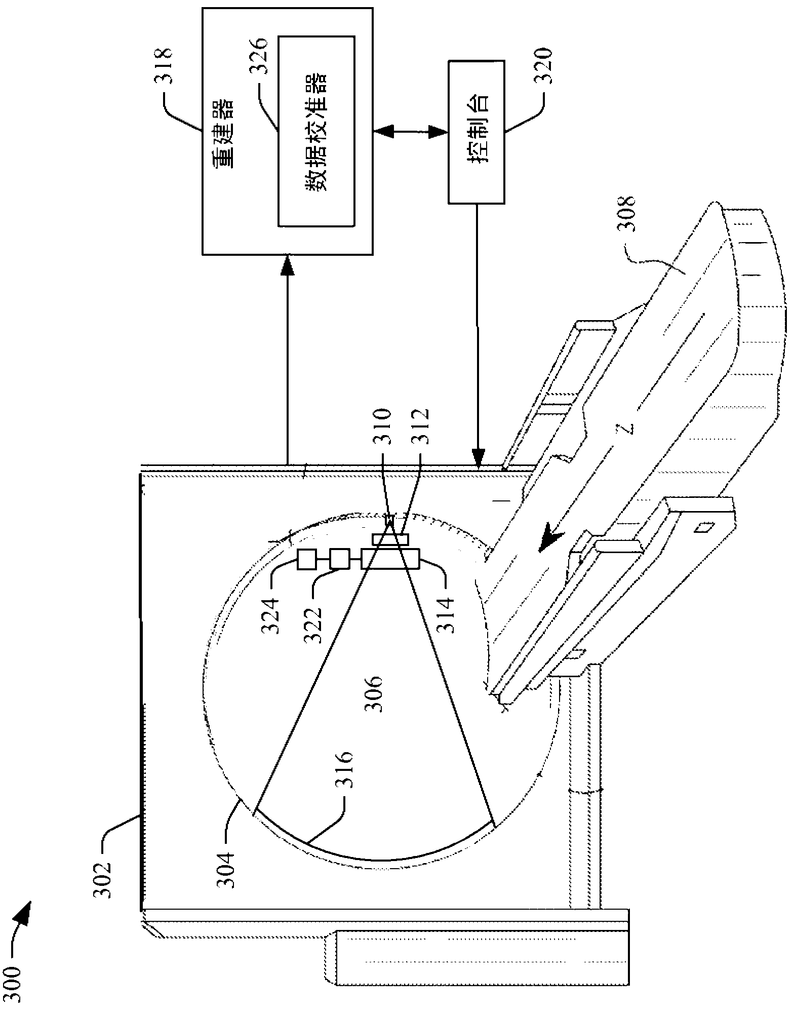
[0020] image 3 An imaging system 300 such as a computed tomography (CT) scanner is illustrated. The imaging system 300 includes a fixed frame 302 and a rotating frame 304 , the rotating frame 304 is rotatably supported by the fixed frame 302 . The rotating gantry 304 rotates about the longitudinal or z-axis about the examination region 306 . A support 308 , such as a recliner, supports the subject in the examination area 306 and may be used to position the subject about the x, y, and / or z axes before, during, and / or after the scan.

[0021] A radiation source 310 , such as an x-ray tube, is supported by the rotating gantry 304 and rotates with the rotating gantry 304 about the examination region 306 and emits radiation through the examination region 306 . A source collimator 312 collimates the emitted radiation to form a beam, typically fan-shaped, conical, or otherwise shaped, across the examination region 306 . A radiation sensitive detector array 316 is located opposite...


PUM


Abstract

An imaging system including a source (310) having a focal spot (406) that emits a radiation beam that traverses an examination region, a radiation sensitive detector array (316) having a plurality of pixels that detects radiation traversing the examination region and generates projection data indicative of the detected radiation, and a filter (314), disposed between the source and the examination region, that filters peripheral regions of the emitted radiation, wherein the filter includes two separate and moveable regions (402), each region having a substantially same thickness and constant homogeneity.

Description

technical field [0001] The following relates generally to the field of imaging, and more specifically to filters for reducing radiation at the edges of radiation beams in computed tomography (CT) scanners. Background technique [0002] A conventional CT scanner includes an x-ray tube that emits radiation. A source collimator is placed between the x-ray tube and the examination region and collimates the emitted radiation to produce a fan or conical x-ray beam. The collimated beam traverses the examination region and the object or subject therein (which attenuates the beam according to the radiation density of the object or subject) and illuminates a detector array opposite the examination region relative to the x-ray tube. The detector produces projection data indicative of the detected radiation, and the projection data is reconstructed to generate volumetric image data indicative of the object or subject. [0003] A so-called bowtie filter is placed between the source col...

Claims


Application Information

Patent Timeline
IPC IPC(8): A61B6/03G21K1/10
CPCG21K1/04A61B6/4021G21K1/10A61B6/032A61B6/4035G01N23/046A61B6/5258
Inventor R·普罗克绍
Owner KONINKLIJKE PHILIPS ELECTRONICS NV
Why Eureka
Try Eureka