Braking device for vehicles

A braking device and vehicle technology, applied in the direction of brakes, braking components, vehicle components, etc., can solve problems such as inability to boost pressure, control, and inability to perform servo pressure, so as to avoid excessive control delay, simplify the structure, and suppress excessive control. delayed effect

Active Publication Date: 2016-11-23
ADVICS CO LTD
View PDF7 Cites 0 Cited by
  • Summary
  • Abstract
  • Description
  • Claims
  • Application Information

AI Technical Summary

Problems solved by technology

[0005] However, if the power supply system fails, the solenoid valve will not be supplied with power, and the control of the servo pressure will not be possible.
That is, it is not possible to electrically control the servo pressure to boost it according to the operation amount of the brake pedal
This results in no braking force in the event of a power failure

Method used


Image

  • Braking device for vehicles
  • Braking device for vehicles
  • Braking device for vehicles

Examples


no. 1 approach 〉

[0039] (Structure of vehicle brake system)

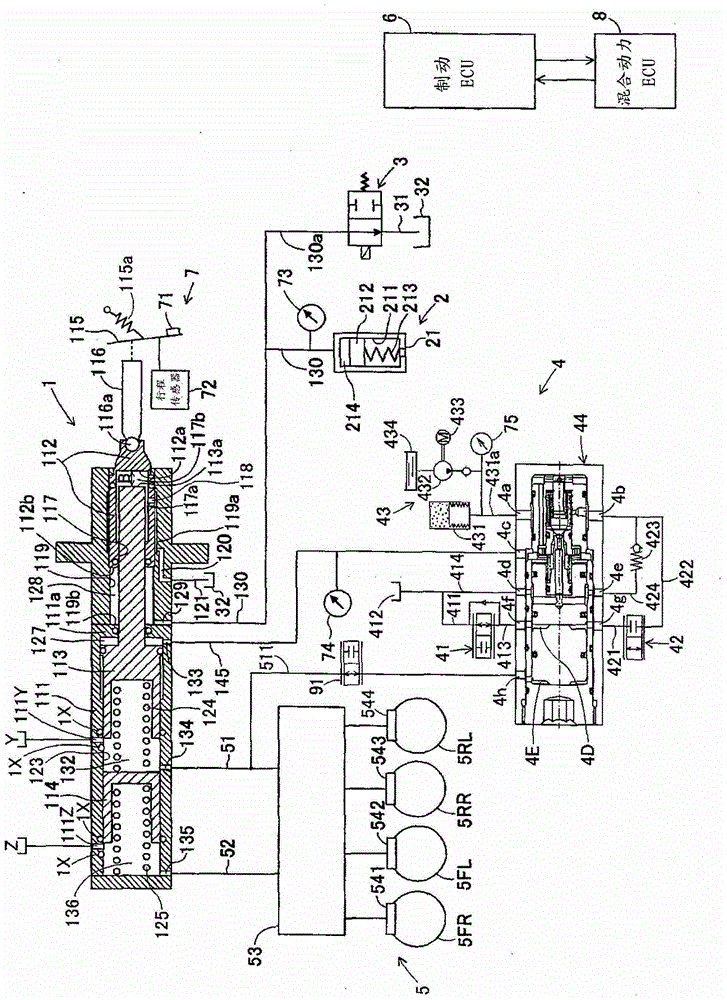
[0040] figure 1 A schematic configuration diagram of a vehicle brake device according to the present embodiment is shown. The brake device for a vehicle according to the present embodiment includes: a master cylinder 1 including master pistons 113, 114 arranged with a distance B in the advancing direction of the input piston 112, and relative to The input piston 112 slides independently along the axial direction; the reaction force generating device 2, the reaction force generating device 2 makes the reaction force chamber 128 generate a reaction pressure corresponding to the movement amount of the input piston 112; the switching valve 3, the switching valve 3 is located at Open path 31, which is branched from the liquid path 130 that communicates the reaction force chamber 128 with the reaction force generating device 2 and communicates with the reservoir 32; booster 4, which is used to generate servo pressure; wheel The brake 5 ...

no. 2 approach 〉

[0093] The vehicle braking device of the second embodiment is as follows: image 3 As shown, in the first embodiment, the restriction valve 91 is arranged on the piping 511 . Therefore, descriptions of other configurations are omitted.

[0094] The restriction valve 91 (corresponding to the “restriction portion”) is a normally open solenoid valve and is disposed on the piping 511 . The limit valve 91 is opened and closed according to a command from the brake ECU 6 . In the linear mode, when the pressure of the second pilot chamber 4E is too high compared with the pressure of the first pilot chamber 4D by the pressure supply unit 43 , the brake ECU 6 issues a closing command to the limit valve 91 .

[0095] In the linear mode, it is conceivable that the pressure of the second pilot chamber 4E is too high compared with the pressure of the first pilot chamber 4D. For example, the pressure of the first pilot chamber 4D suddenly drops due to control, and the pressure of the first...

no. 3 approach 〉

[0100] The vehicle braking device of the third embodiment is as follows: Figure 4 As shown, in the first embodiment, an orifice (orifice) 92 is disposed on the pipe 511 . Therefore, descriptions of other configurations are omitted.

[0101] The orifice 92 (corresponding to a “restriction portion”) is arranged on the pipe 511 and restricts the flow of the brake fluid in the pipe 511 . The orifice 92 suppresses a sudden flow of the brake fluid in the pipe 511 by making it difficult for the brake fluid to leak all at once. Specifically, the orifice 92 slows down the depressurization speed of the second pilot chamber 4E due to the pressurization operation of the ABS 53 . By preventing the sudden drop in pressure of the second pilot chamber 4E, it is possible to allow time margin for the pressure control of the first pilot chamber 4D with respect to the drop in pressure of the second pilot chamber 4E. For example, in the control to increase the pressure of the first pilot chamb...


PUM


Abstract

The present invention provides a brake device for a vehicle capable of exhibiting a braking force corresponding to the amount of operation of a brake operating member even when a power supply system fails. The vehicle braking device of the present invention includes: a master cylinder (1), the master piston of which is driven to move by the servo pressure in the servo chamber, and the main pressure of the master chamber pressure changes through the movement of the master piston; the mechanical servo pressure generates device (44), the rest of the high-pressure source is connected to the servo chamber, and based on the brake fluid pressure of the high-pressure source, the servo chamber generates a servo pressure corresponding to the pilot pressure in the pilot chamber; it is connected with the pilot chamber to generate the required pilot pressure in the pilot chamber The electric pilot pressure generating device (41, 42, 43); the main pilot room brake fluid path (511) connecting the main chamber and the pilot chamber, and the vehicle braking device uses the pilot pressure when the power system is normal. The generating device generates pilot pressure, and the main pressure is used as the pilot pressure when the power system fails.

Description

technical field [0001] The present invention relates to a vehicle brake device that controls a braking force applied to a vehicle based on a driver's brake operation amount. Background technique [0002] As an example of a vehicle brake device that controls the braking force applied to the vehicle according to the driver's brake operation amount, there are known, for example, Japanese Patent Application Laid-Open No. 2010-167915 (Patent Document 1), Japanese Patent Laid-Open No. 9- The brake device for a vehicle cited in Publication No. 328069 (Patent Document 2). The above-mentioned vehicle braking device applies a braking force based on control oil pressure generated by an accumulator and a solenoid valve to the wheel cylinders in accordance with the movement of the input piston. [0003] [Patent Document 1] Japanese Patent Laid-Open No. 2010-167915 [0004] [Patent Document 2] Japanese Patent Application Laid-Open No. 9-328069 [0005] However, when the power supply sy...

Claims


Application Information

Patent Timeline
Patent Type & Authority Patents(China)
IPC IPC(8): B60T1/08
CPCB60T8/4077B60T13/147B60T13/142
Inventor 增田芳夫新野洋章黑川卓
Owner ADVICS CO LTD
Why Eureka
Try Eureka